Control method of magnet type fan clutch

a control method and fan technology, applied in mechanical actuated clutches, machines/engines, roads, etc., can solve the problems of reducing the life of electromagnetic clutches, and reducing the efficiency of electromagnetic clutches. the effect of reducing the capacity of electromagnetic clutches

Inactive Publication Date: 2006-06-15
USUI KOKUSAI SANGYO KAISHA LTD
View PDF52 Cites 8 Cited by
  • Summary
  • Abstract
  • Description
  • Claims
  • Application Information

AI Technical Summary

Benefits of technology

[0012] According to the method of the present invention, in a magnet type fan clutch, wherein a magnet coupling is combined with an electromagnetic clutch; a fan is attached to the magnet coupling side; and the magnet coupling is ON and OFF-controlled by the electromagnetic clutch; by controlling ON timing of the electromagnetic clutch and connection of the clutch using a radiator cooling fluid temperature, an engine oil temperature, a transmission oil temperature, a vehicle speed, an engine rotation rate, an accelerator (throttle) opening, a compressor pressure of an air conditioner and an On or Off signal of the air conditioner, an engine rotation acceleration, an accelerator opening acceleration, and a fuel injection indication

Problems solved by technology

However, according to the control method of the viscous fluid joint of a system that the valve is opened or closed by transformation of the bimetal reacting to a temperature of a radiator passing wind to fluctuate the oil supply amount and change the fan rotation, it is not possible to make the temperature of an engine cooling fluid deciding an engine cooling performance into a direct control object, so that this involves disadvantages such that a loss of horsepower is generated due to an unnecessary fan rotation, a lower fuel economy is caused, a g

Method used


Image

  • Control method of magnet type fan clutch
  • Control method of magnet type fan clutch
  • Control method of magnet type fan clutch

Examples


Embodiment Construction

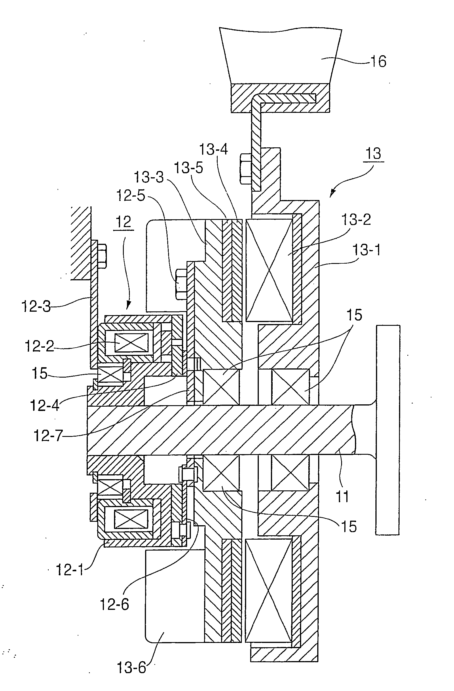
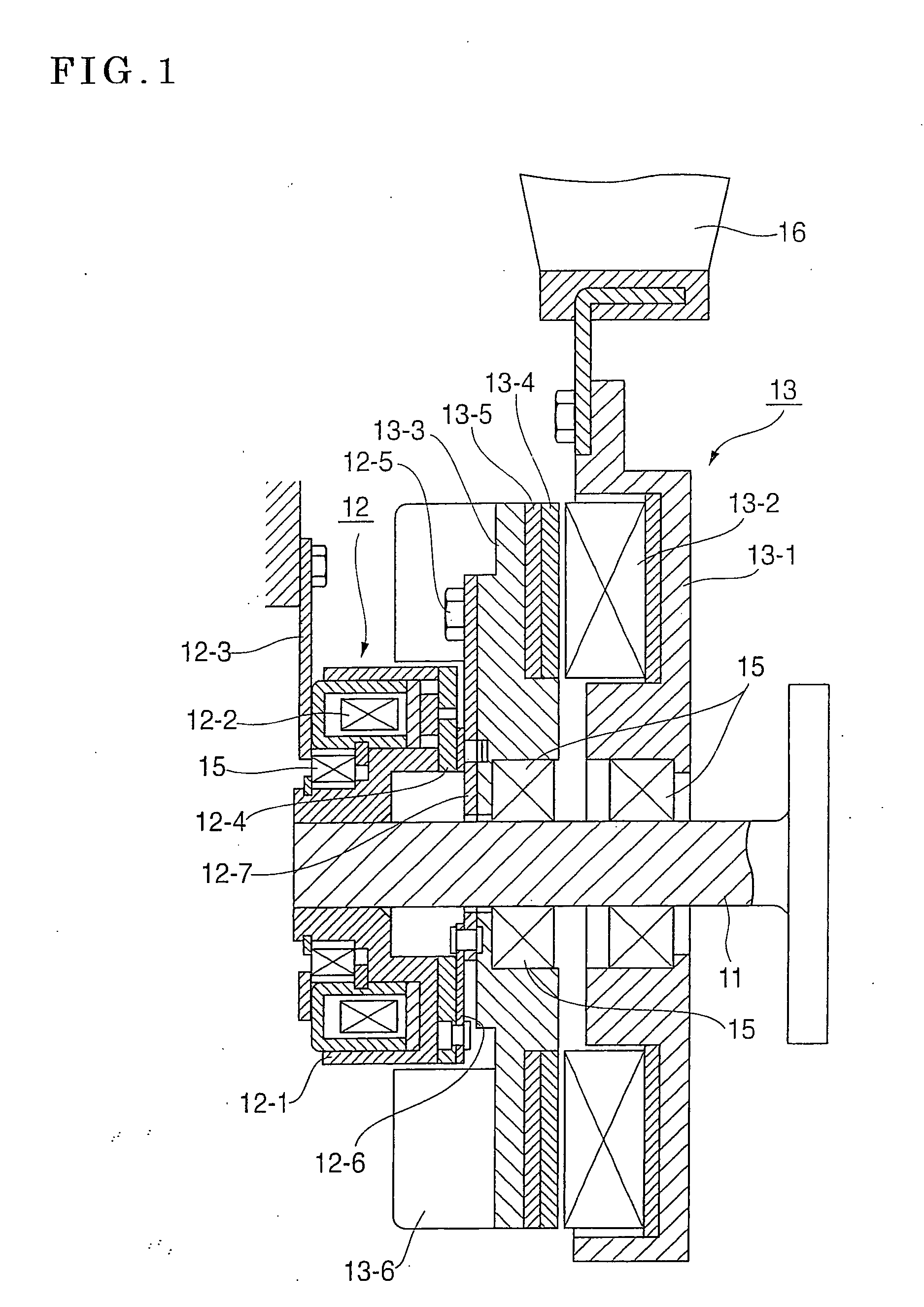
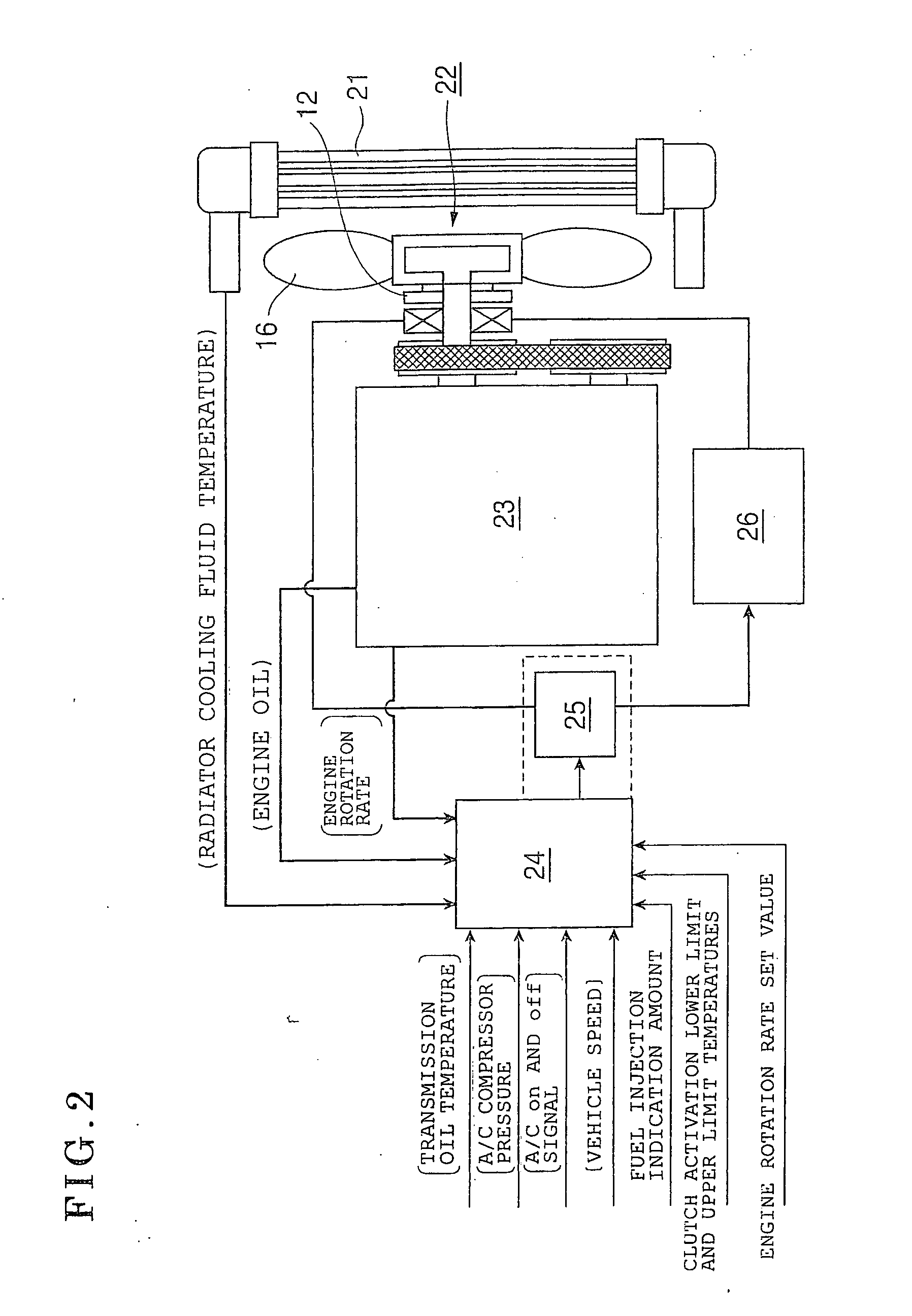
[0020]FIG. 1 is a longitudinal sectional view showing an embodiment of a magnet type fan clutch according to the present invention, FIG. 2 is a schematic diagram showing an example of the entire structure of a control system for putting a control method of the magnet type fan clutch shown in FIG. 1 in execution, FIG. 3 is a flow chart showing an embodiment of the control method of this magnet type fan clutch, and FIGS. 4 to 7 show a fan rotation control example of this magnet type fan clutch.

[0021] The magnet type fan clutch shown in FIG. 1 is configured by an electromagnetic clutch 12 arranged in one piece of a driving shaft 11 and a magnet coupling 13. The electromagnetic clutch 12 is configured by a clutch rotor 12-1 that is integrally supported by an end portion of the driving shaft 11 and an excitation coil 12-2 that is fit in this clutch rotor 12-1 via a bearing device 15 rotatably with each other and is fixed to the exterior via a bracket 12-3, and an armature 12-4 that is m...


PUM


Abstract

A control method of a magnet type fan clutch is provided to improve engine performance, fuel economy, engine life, and vehicle acceleration and to reduce fan noise, and optimize fan horsepower. The magnet type fan clutch has a magnet coupling combined with an electromagnetic clutch. The method includes turning the electromagnetic clutch ON and OFF on the basis of cooling fluid temperature, engine oil temperature, transmission oil temperature, vehicle speed, engine rotation rate, accelerator opening, compressor pressure of an air conditioner, an On or Off signal of the air condition, a fuel injection indication amount, a clutch activation lower limit temperature and its lower temperature, and an engine rotation rate set value to control the fan rotation.

Description

BACKGROUND OF THE INVENTION [0001] 1. Field of the Invention [0002] The present invention relates to a control method of a magnet type fan clutch which controls rotation of a cooling fan to be mainly applied to an internal combustion engine for vehicles, and more specifically to a control method of a magnet type fan clutch, which is configured in such a manner that a magnet coupling and an electromagnetic clutch are integrated with each other and the magnet coupling is controlled so as to be turned on and off by the electromagnetic clutch. [0003] 2. Description of Related Art [0004] As a magnet type fan clutch which controls rotation of a cooling fan to be applied to an internal combustion engine for vehicles, in JP-A-9-119455, a viscous fluid joint which transmits an output drive torque to a radiator cooling fan by a driving torque from an engine for vehicle and its control method are disclosed. This viscous fluid joint takes a system for fluctuating an oil supply amount when a val...

Claims


Application Information

Patent Timeline
IPC IPC(8): F16D27/01
CPCF04D25/026Y02T10/76Y10T477/753Y10T477/76F04D27/008F16D27/12F16D27/01F16D27/105
Inventor INOUE, HIROSHISHIOZAKI, KEN
Owner USUI KOKUSAI SANGYO KAISHA LTD
Why Eureka
Try Eureka