Nonaqueous electrolyte secondary cell

a secondary battery and electrolyte technology, applied in the field of non-aqueous electrolyte secondary batteries, can solve the problems of insufficient practical use, poor cycle performance of secondary batteries using these materials as negative electrodes, and change in volume, so as to reduce the manufacturing time and cost of negative electrodes, reduce the swelling of batteries, and reduce the effect of particle size control

Inactive Publication Date: 2006-06-15
GS YUASA INT LTD
View PDF4 Cites 26 Cited by
  • Summary
  • Abstract
  • Description
  • Claims
  • Application Information

AI Technical Summary

Benefits of technology

[0008] According to the present invention, both high energy density and satisfactory cycle performance can be provided.
[0010] With this ratio being adopted, battery swelling can be reduced in the charge / discharge process at a low temperature not higher than 0° C. and, in addition, the alloy can be ground readily, so that its particle size control becomes easy, and this makes it possible to reduce the negative electrode manufacturing time and the cost.
[0011] In addition, it is preferable that the above described composite layer contain carbon material, thereby allowing battery swelling to be much more reduced in the charge / discharge process at a low temperature not higher than 0° C. When carbon material is contained, supposing that n1 is the mass of the above described alloy, n2 is the mass of carbon material, and S=n1 / n2, it is more preferable that S fall within the range of 0.05≦S≦3.5. This allows battery swelling in the charge process at a low temperature to be much more reduced.
[0012] In addition, when powdered negative active material is used in a composite layer, it is preferable that the porosity of the above described composite layer be 30 to 75%. The reason for this is that cycle performance and energy density can be further enhanced.
[0013] In addition, it is preferable that the apparent density of the above described negative electrode be 2.5 to 8.3 g / cm3. The reason for this is that cycle performance and energy density can be further enhanced.

Problems solved by technology

However, these materials suffer significant changes in volume due to alloying; hence, the secondary batteries using these materials as a negative electrode are poor in cycle performance and insufficient for practical use.
And, as a result, he has found that it is impossible to attain sufficient cycle performance only by mixing Sn and Ni and perform reversible charge / discharge by using a complete alloy of Sn and Ni, for example, Sn4Ni3 alloy, and that when an alloy having Sn phase and Sn4Ni3 phase is used, it is possible to realize satisfactory cycle performance and high energy density.

Method used


Image

  • Nonaqueous electrolyte secondary cell
  • Nonaqueous electrolyte secondary cell
  • Nonaqueous electrolyte secondary cell

Examples


embodiment 1

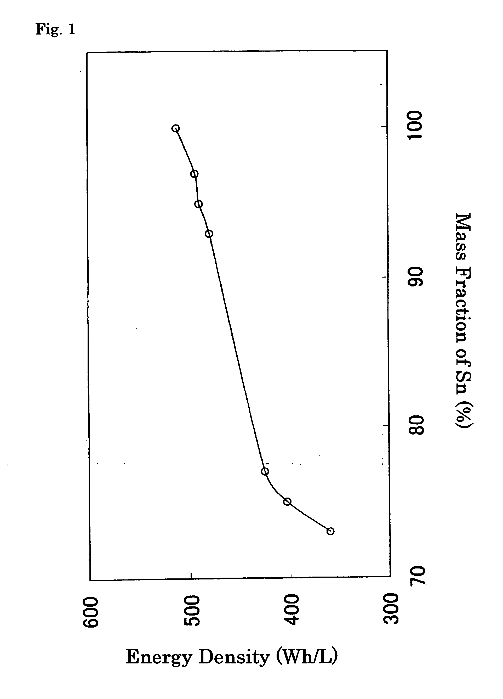
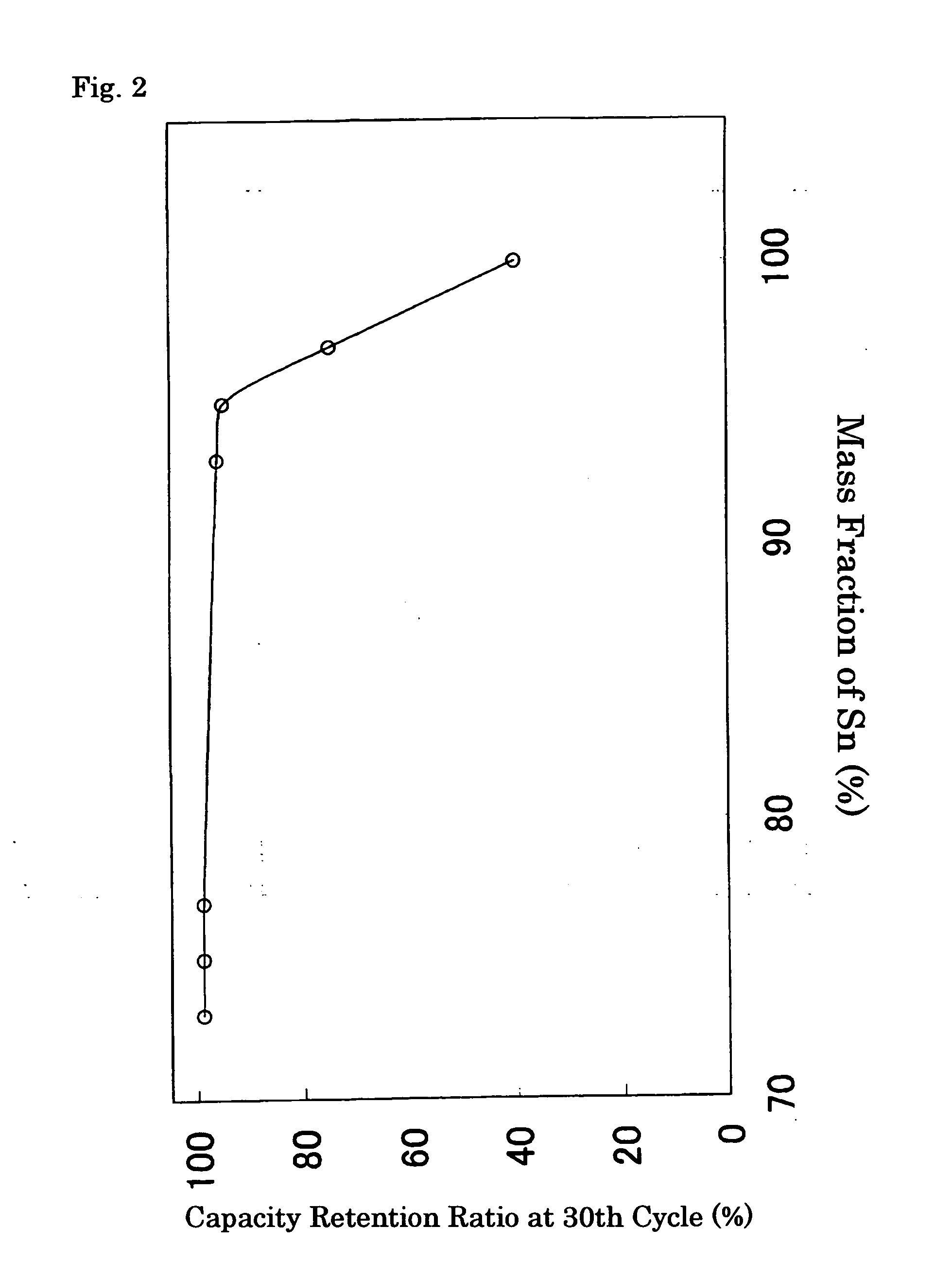
[0059] In this example, Sn powder and Ni powder were weighed out to 95 mass % and 5 mass %, respectively, and preparatively mixed in a mortar. This mixed powder and SUS balls for ball-milling were enclosed in a SUS hermetically-sealed container for the ball-milling under an argon atmosphere. Subsequently, this container was set in a planetary ball mill, the powder inside was milled for 30 minutes, and the obtained powder was dried at 150° C., thereby producing an alloy containing 95 mass % of Sn and 5 mass % of Ni. This alloy was used as the negative active material.

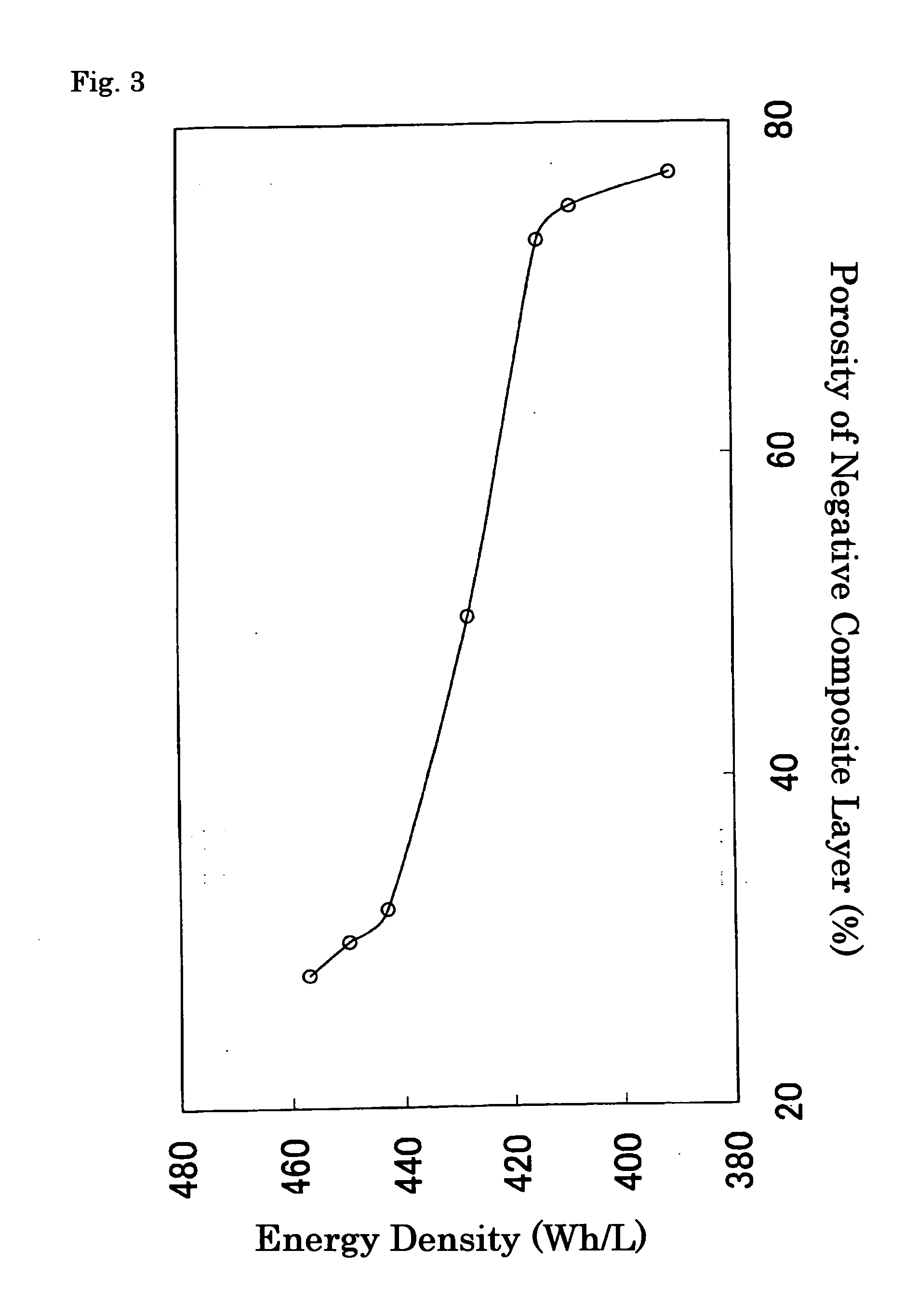
[0060] A paste was mixed and prepared so as to consist of 45 mass % of the powdered negative active material above described, 10 mass % of PVdF as a binder and 45 mass % of N-methyl-2-pyrrolidone (NMP) a applied to both surfaces of Cu foil of 27 mm in width and 10 μm in thickness; the coated foil was dried at 150° C. to evaporate NMP and then pressed to adjust the porosity; and thus the negative electrode was produced. ...

embodiments 2 to 4

[0064] To these examples, alloy compositions shown in Table 1 were applied, where the weighing amounts of Sn powder and Ni powder were varied in the course of the preparation of the negative active material; except for the above, Batteries (B) to (D) of Embodiments 2 to 4 were manufactured in an identical manner to that of Embodiment 1.

embodiment 5

[0078] In this example, Cu foil of 27 mm in width and 14 μm in thickness was immersed in a commercially-manufactured Sn—Ni plating solution (Kojundo Chemical Lab. Co., Ltd., SNS-200E). After that, using the Sn—Ni alloy containing 28 mass % of Ni in the counter electrode, electricity was conducted so that the cathode current density becomes 2 A / dm3, and Sn—Ni alloy was synthesized on the Cu foil. After washed with ion exchange water, this material was dried at 150° C., and thus the negative electrode was prepared. As a result of conducting the quantitative analysis of element, the composition of this Sn—Ni alloy was found to be 85 mass % of Sn and 15 mass % of Ni. In addition, in the X-ray diffraction pattern of this Sn—Ni alloy, the peaks due to CuKα radiation lay at 20=30.30 and 30.60. Except for using this negative electrode, Battery (J) of Embodiment 5 was manufactured in an identical manner to that of Embodiment 1.


PUM

PropertyMeasurementUnit
porosityaaaaaaaaaa
temperatureaaaaaaaaaa
apparent densityaaaaaaaaaa

Abstract

It is an object of the present invention to provide a non-aqueous electrolyte secondary battery having high energy density and satisfactory cycle performance by using an alloy comprising Ni and Sn as a negative active material; and the non-aqueous electrolyte secondary battery comprising a negative electrode with a composite layer containing a negative active material, a positive electrode and a non-aqueous electrolyte is characterized in that said negative active material consists of an alloy containing 5 to 25 mass % of nickel and 75 to 95 mass % of tin, and that such alloy contains Sn4Ni3 phase and Sn phase. It is preferable that the content ratio of Sn4Ni3 phase and Sn phase in the above described alloy be 0.2≦Z≦3, supposing that ml is the mass of Sn4Ni3 phase, m2 is the mass of said Sn phase, and Z=m1 / m2; and that the above described composite layer contain carbon material.

Description

TECHNICAL FIELD [0001] The present invention relates to a non-aqueous electrolyte secondary battery. BACKGROUND ART [0002] In recent years, in order to meet the demand for ever smaller, more functional portable devices, studies on further improving the energy density of the secondary batteries to be installed on such devices have been conducted vigorously. [0003] A lithium-ion secondary battery having a lithium transition metal oxide positive electrode and a graphitic carbon negative electrode can be a typical example of high energy density secondary batteries. And, aiming for the realization of much higher energy density, the use of metal materials such as Al, Sn and Si, capable of alloying with Li, as a negative electrode is being considered. [0004] However, these materials suffer significant changes in volume due to alloying; hence, the secondary batteries using these materials as a negative electrode are poor in cycle performance and insufficient for practical use. Some proposal...

Claims


Application Information

Patent Timeline
Patent Type & Authority Applications(United States)
IPC IPC(8): H01M4/38H01M4/02H01M4/134H01M10/0525H01M10/36
CPCH01M4/134H01M4/38H01M10/0525H01M2004/027Y02E60/122H01M4/387Y02E60/10
Inventor YAMATE, SHIGEKI
Owner GS YUASA INT LTD
Why Eureka
Try Eureka