Acceleration sensor manufactureable by simplified method

a manufacturing method and acceleration sensor technology, applied in the direction of acceleration measurement in multiple dimensions, acceleration measurement using interia forces, instruments, etc., can solve the problems of inefficiency, high cost, and time-consuming deposition, and achieve the effect of simplifying the manufacture of acceleration sensors

Inactive Publication Date: 2006-06-22
LAPIS SEMICON CO LTD
View PDF2 Cites 12 Cited by
  • Summary
  • Abstract
  • Description
  • Claims
  • Application Information

AI Technical Summary

Benefits of technology

[0007] An object of the present invention is to simplify the manufacture of an acceleration sensor.

Problems solved by technology

A problem with this acceleration sensor is that in order to obtain an impact resistance rating of at least 6000 G, the conventional stopper structure requires the deposition of an aluminum reinforcing film at least several tens of micrometers thick.
If this film is deposited by one of the processes commonly used in semiconductor fabrication, e.g., a sputtering process, deposition takes much time and the acceleration sensor cannot be manufactured efficiently.
Additional mask deposition and patterning steps are also required, making the manufacturing process still more time-consuming, complex, and expensive.

Method used


Image

  • Acceleration sensor manufactureable by simplified method
  • Acceleration sensor manufactureable by simplified method
  • Acceleration sensor manufactureable by simplified method

Examples


first embodiment

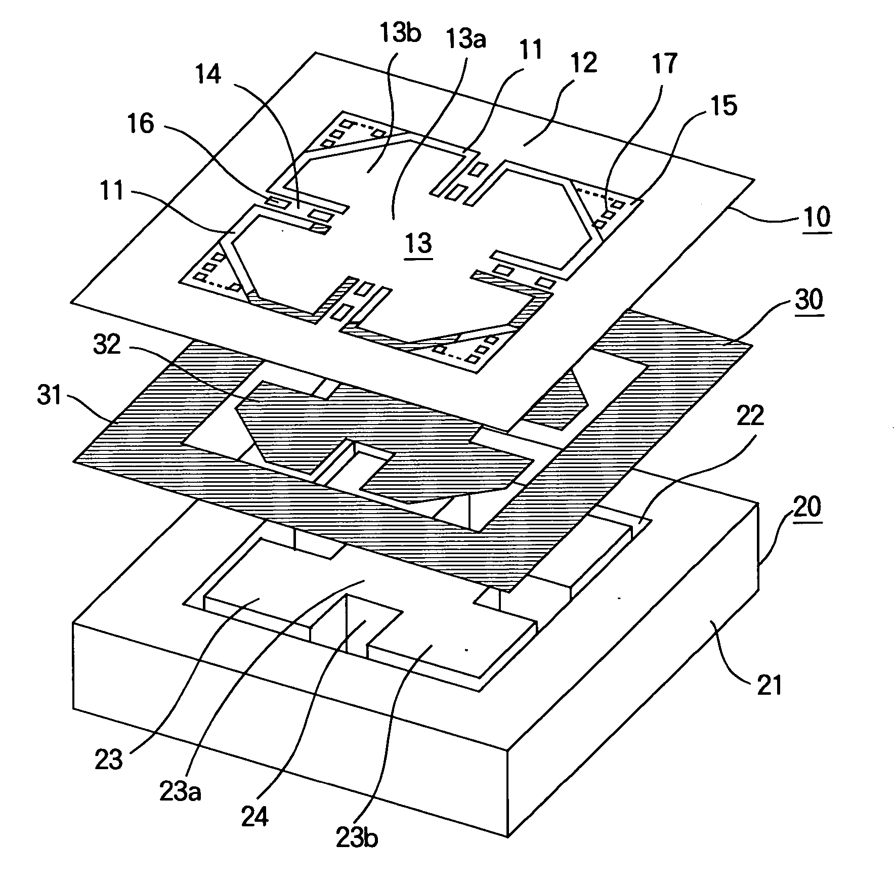
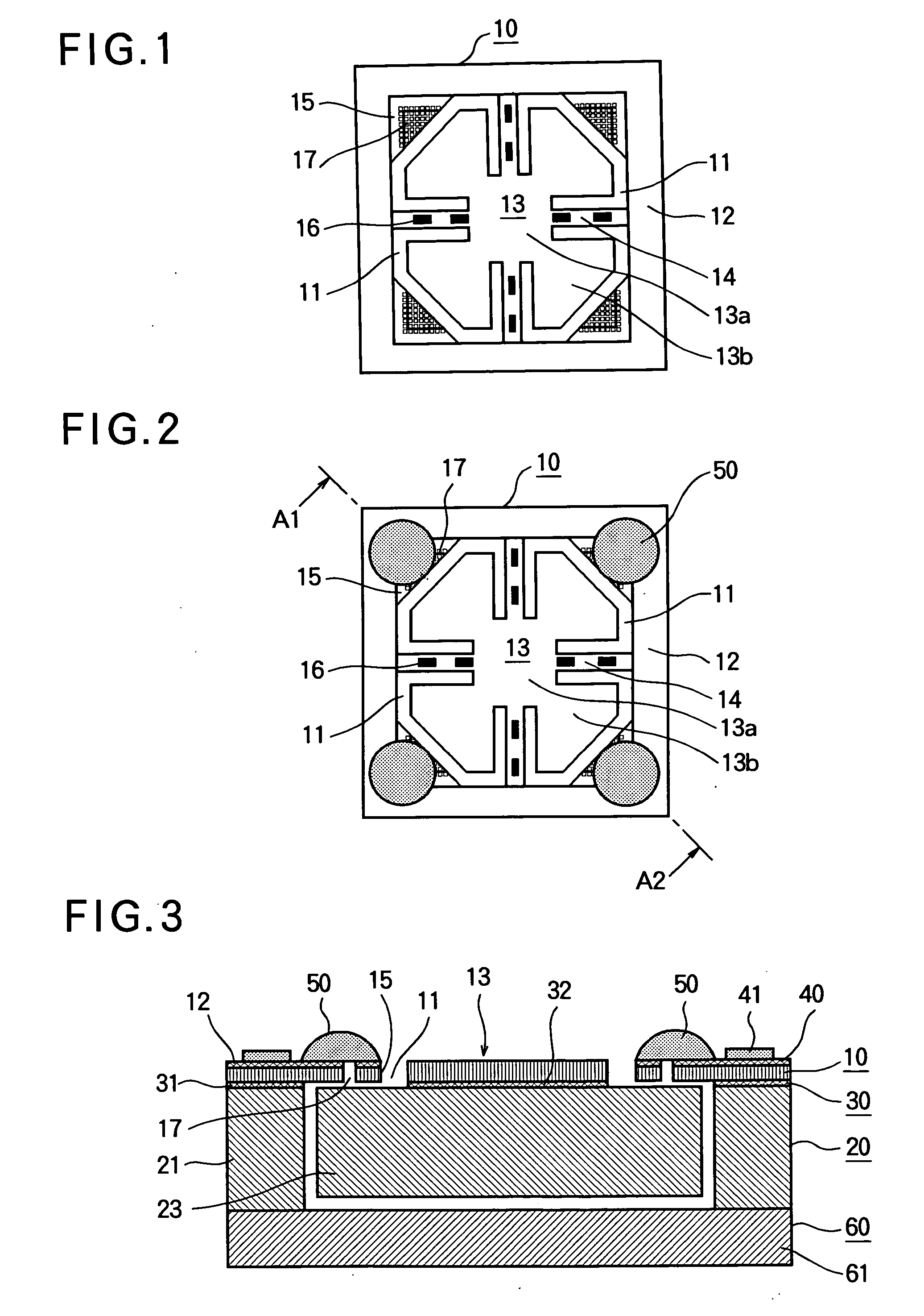
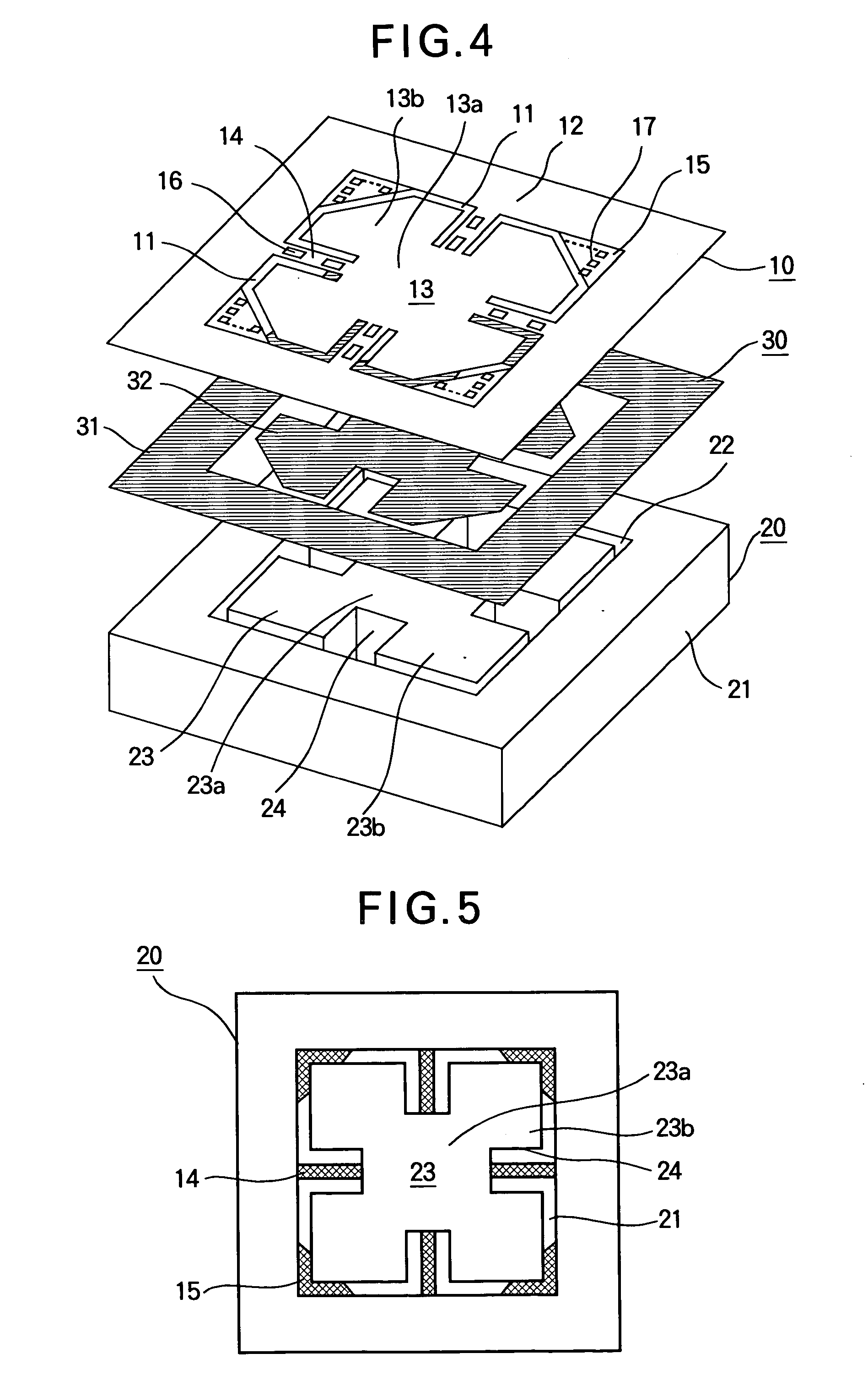
[0031] A first embodiment will be described with reference to the top plan views in FIGS. 1 and 2, the sectional view in FIG. 3, the perspective view in FIG. 4, and the bottom plan view in FIG. 5.

[0032] The first embodiment is an acceleration sensor formed in a silicon-on-insulator (SOI) wafer by etching and other processes. The SOI wafer includes a first silicon substrate 10 approximately ten micrometers (10 μm) thick, a second silicon substrate 20 approximately 525 μm thick, and an insulating bonding layer 30 by which the first silicon substrate 10 and second silicon substrate 20 are joined.

[0033] The first silicon substrate 10 of a single acceleration sensor has a substantially square shape measuring about two and a half millimeters (2.5 mm) on a side, in which four openings or trenches 11 are provided to define a peripheral attachment section 12, a mass attachment section 13, beams 14, and stoppers 15. The peripheral attachment section 12 is an area approximately 500 μm wide, ...

second embodiment

[0064] In a second embodiment, the silicone rubber reinforcement is applied as a plurality of drops (for example, three drops 50-1, 50-2, 50-3 as shown in FIG. 20) to each of the stoppers 15 from the dispenser 70. Otherwise, the structure and manufacturing method are the same as in the first embodiment.

[0065] In the first embodiment, since the silicone rubber 50 is applied as one drop, a height of, for example, 250 μm or more is required for adequate reinforcement, and the package 60 must be thick enough to accommodate this height. In the second embodiment, since the silicone rubber applied to each stopper 15 is dispensed from the dispenser 70 as a plurality of smaller drops 50-1 to 50-3, the heights of the drops can be reduced to as little as about 150 μm while still providing adequate reinforcement, so the thickness of the package 60 can be reduced. Impact resistance is also improved in that the reinforcement is spread over a wider area of the stoppers 15.

third embodiment

[0066] In a third embodiment, silicone rubber 50A is applied by the dispenser 70 as a swath covering at least part of all of the stoppers 15 and part of the adjacent surface of the peripheral attachment section 12 to reinforce the stoppers 15 and peripheral attachment section 12. As shown in FIG. 18, for example, if the dispenser 70 moves in a line along the peripheral attachment section 12, starting from one stopper 15 and ending at another stopper 15, the silicone rubber 50A can be applied as a single continuous swath. In this case, a uniform swath of silicone rubber 50A can be applied by lifting the dispenser 70 away from the peripheral attachment section 12 as the dispenser 70 retraces the final part of the swath, moving backward from the final application point.

[0067] In FIG. 21, since the silicone rubber 50A is not applied in a complete loop, there is a part of the peripheral attachment section 12 to which no silicone rubber is applied. Electrical interconnection terminals ca...


PUM


Abstract

An acceleration sensor has a mass movably linked to a peripheral attachment section to which at least one stopper is attached to stop the motion of the mass in a certain direction. In the absence of acceleration, the mass rests at a distance from a first surface of the stopper. A quantity of a curable elastic adhesive on a second surface of the stopper absorbs impact of the mass on the first surface, enabling the acceleration sensor to survive mechanical shock. The curable elastic adhesive may adhere to the cover of a package in which the acceleration sensor is enclosed. The curable elastic adhesive may be applied as a drop or swath from a dispenser, which simplifies the manufacturing process and reduces the manufacturing cost.

Description

BACKGROUND OF THE INVENTION [0001] 1. Field of the Invention [0002] The present invention relates to a three-axis (XYZ) acceleration sensor and its method of manufacture, more particularly to a simplified method of providing improved impact resistance. [0003] 2. Description of the Related Art [0004] Technology for making an acceleration sensor resistant to destruction by impact is described in, for example, Japanese Patent Application Publication No. 2004-198243. The acceleration sensor described therein has a mass attachment section, a peripheral attachment section surrounding the mass attachment section, beams flexibly linking the mass attachment section to the peripheral attachment section, resistive elements disposed on the surfaces of the beams and producing piezoresistive effects, a mass secured to the mass attachment section, a frame securing the peripheral attachment section to its package so that the rest position of the mass is a prescribed distance above the floor of the ...

Claims


Application Information

Patent Timeline
Patent Type & Authority Applications(United States)
IPC IPC(8): G01P15/00G01P15/02G01P15/08G01P15/12G01P15/18H01L29/84
CPCB81B3/0051B81B7/0012B81B2201/0235G01P1/023G01P15/0802G01P15/123G01P15/18G01P2015/084G01P2015/0842G01P3/488
Inventor IKEGAMI, NAOKATSU
Owner LAPIS SEMICON CO LTD
Why Eureka
Try Eureka