Flexible mold, method of manufacturing same and method of manufacturing fine structures
a flexible mold technology, applied in the field of mold and mold manufacturing method, can solve the problems of difficult mass production of molding material or molds containing lithium perchlorate, and the problem of remaining a problem to be solved, and achieve the effect of high oxidative property
- Summary
- Abstract
- Description
- Claims
- Application Information
AI Technical Summary
Benefits of technology
Problems solved by technology
Method used
Image
Examples
example 1
Fabrication of the Flexible Mold:
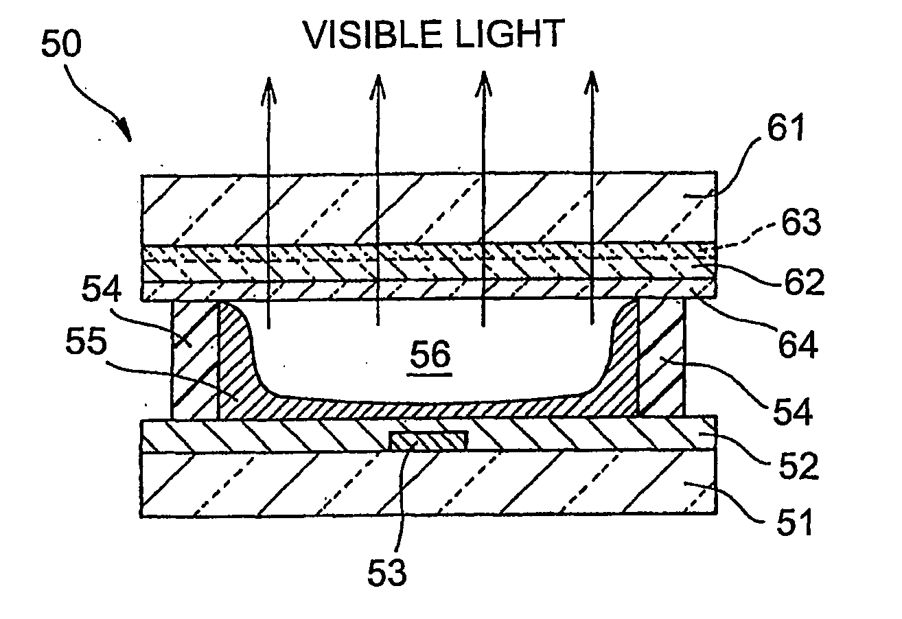
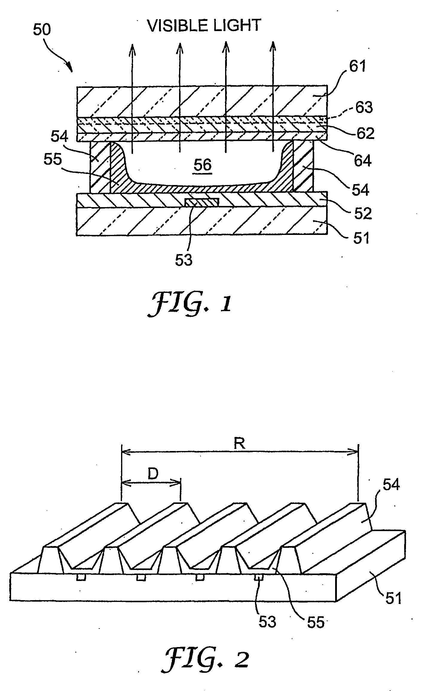
[0096] For the manufacture of back panel for PDP, a rectangular metal master pattern having ribs (partition walls) in a straight pattern was prepared. More specifically, the metal master pattern had ribs with the cross section along the longitudinal direction in the shape of isosceles trapezoid arranged at a constant pitch. The space (recess) defined by adjoining ribs corresponds to a discharge cell for display for PDP. Each of the ribs was 135 μm in height, 60 μm in top width, and 120 μm in bottom width. Pitch (distance between the centers of adjoining ribs) was 300 μm, and number of ribs was 3000. Total pitch (distance between the centers of ribs at both ends) was 900.221 mm.
[0097] In order to be used in forming the mold layer of the mold, a photocurable resin was prepared by mixing aliphatic urethane acrylate oligomer (manufactured by Daicel-UCB, Co.), phenoxyethyl acrylate, and 2-hydroxy-2-methyl-1-phenyl-propane-1-one (photoinitiator: Trade n...
example 2
[0117] The procedure described in Example 1 was repeated to fabricate a flexible mold. In the present Example, in order to evaluate the effect of concentration of lithium salt solution and added amount of the solution relative to the amount of resin upon surface resistance of the mold, lithium salt solutions of different concentration, as shown in FIG. 7, that is:
[0118] C1 . . . 1% by weight propylene carbonate solution
[0119] C2 . . . 2% by weight propylene carbonate solution
[0120] C5 . . . 5% by weight propylene carbonate solution
[0121] C10 . . . 10% by weight propylene carbonate solution
[0122] C20 . . . 20% by weight propylene carbonate solution
were used, and blended amount of the lithium salt solution relative to the amount of resin was also varied in the range of 1 to 5% by weight.
[0123] After each of the lithium salt solutions was blended to resin in different blending amount to prepare UV-curable resin, each of the UV-curable resins was coated to PET film of 100 μm in ...
example 3
[0125] The procedure described in Example 1 above was repeated to fabricate a flexible mold. In the present Example, in order to evaluate the effect of blended amount of lithium salt solution relative to total amount of resin upon electrification voltage of the mold, lithium salt solution in the form of 20% by weight propylene carbonate solution (C20) was used and the blended amount of the lithium salt solution relative to total amount of resin was varied in the range of 0.0 to 2.0% by weight.
[0126] After UV-curable resin was prepared by blending the lithium salt solution in different blended amount, each UV-curable resin was coated to a PET film of 100 μm in thickness and was irradiated with UV light to form the mold with a mold layer of 300 μm in thickness.
[0127] Next, each mold was cut to form a test specimen of length 850 mm×width 350 mm. On this test specimen of mold layer, a PET film (Trade name “HPE”: manufactured by Teijin Co.) of same size as the test specimen and 100 μm ...
PUM
| Property | Measurement | Unit |
|---|---|---|
| Temperature | aaaaa | aaaaa |
| Thickness | aaaaa | aaaaa |
| Thickness | aaaaa | aaaaa |
Abstract
Description
Claims
Application Information
 - R&D
- Intellectual Property
- Life Sciences
- Materials
- Tech Scout
- Unparalleled Data Quality
- Higher Quality Content
- 60% Fewer Hallucinations
Browse by: Latest US Patents, China's latest patents, Technical Efficacy Thesaurus, Application Domain, Technology Topic, Popular Technical Reports.
© 2025 PatSnap. All rights reserved.Legal|Privacy policy|Modern Slavery Act Transparency Statement|Sitemap|About US| Contact US: help@patsnap.com


