System and method to decrease probe size for improved laser ultrasound detection

a laser ultrasound and probe technology, applied in the field can solve the problems of adversely increasing the manufacturing cost associated with composite structures, requiring strict quality control procedures in the manufacturing process, and reducing so as to achieve the effect of increasing the efficiency of ultrasound generation and detection, and being easy to us

Inactive Publication Date: 2006-06-22
LOCKHEED MARTIN CORP
View PDF6 Cites 15 Cited by
  • Summary
  • Abstract
  • Description
  • Claims
  • Application Information

AI Technical Summary

Benefits of technology

[0014] Another embodiment of the present invention provides a method for performing ultrasonic measurements for generating and measuring ultrasonic displacements on the surface of the target. This method involves generating the ultrasonic displacements at the surface of the target or work piece. This may be done using a generation laser beam provided via a compact optical probe or other means known to those skilled in the art. Next an illumination laser beam illuminates the ultrasonic displacements at the surface of the work piece. This illumination laser beam may also be provided via the same compact optical probe. The illumination laser beam is scattered by the ultrasonic surface displacements to produce phase modulated light which may then be collected by the compact optical probe. The compact optical probe may include angle-terminated optical fibers for the illumination laser beam, generation laser beam, and to collect phase modulated light. The phase modulated light may then be processed to obtain data representative of ultrasonic ...

Problems solved by technology

While composite materials offer significant improvements in performance, they require strict quality control procedures in the manufacturing processes.
Conventional NDE methods are slow, labor-intensive, and costly.
As a result, testing procedures adversely increase the manufacturing costs associated with composite structures.
Additionally, laser ultrasound may provide low sensitivity to the orientation of the sample relative to the illuminating laser beam.
However due to the complex shapes often inspected, it is difficult to realize a line of sight from the laser source to the sample being inspected.
These different optical setups can cause the laser ultrasound probe to become cumbersome.
Additionally, system optics associated with ultrasound generation, detection, and collection in the path of one another may decrease the optical efficiency of the system while increasing the size and complexity.
However, the use of multiple devices increases the time to perform inspections,...

Method used


Image

  • System and method to decrease probe size for improved laser ultrasound detection
  • System and method to decrease probe size for improved laser ultrasound detection
  • System and method to decrease probe size for improved laser ultrasound detection

Examples


Embodiment Construction

[0026] Embodiments of the present invention are illustrated in the FIGs, like numerals being used for like and corresponding parts of the various drawings.

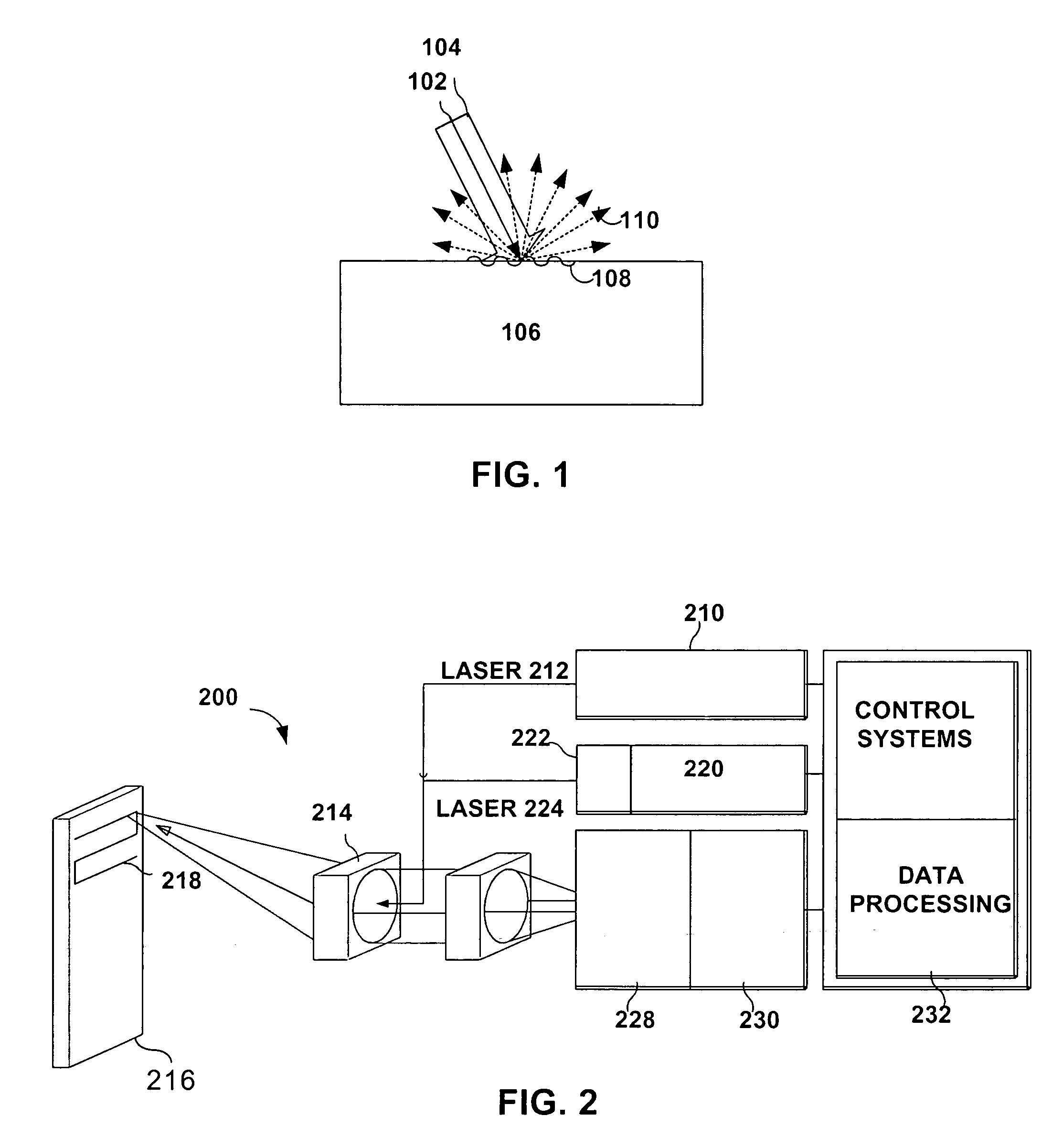
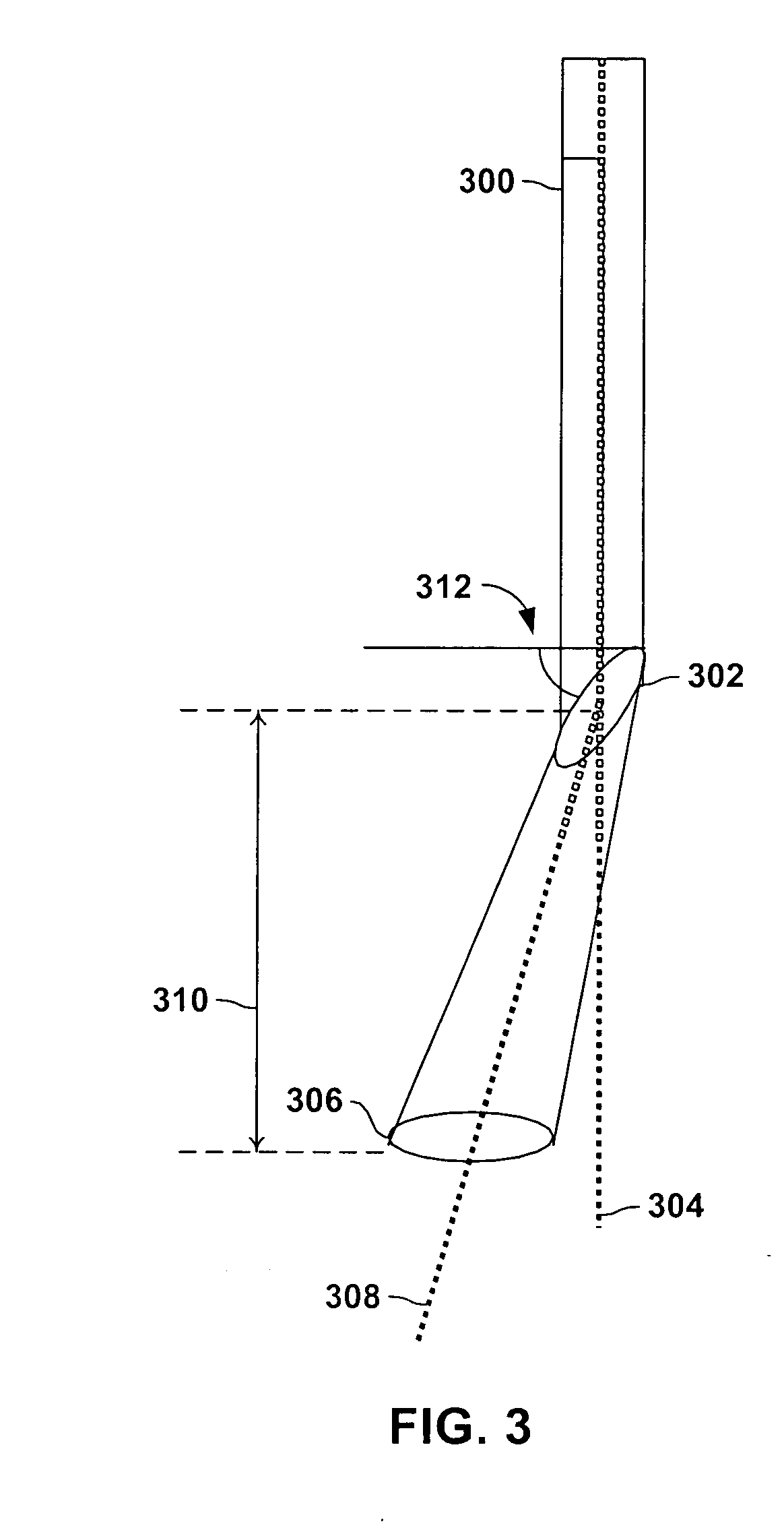
[0027] The present invention provides the ability to use the same optics for generation, detection and collection of laser light associated with a laser ultrasound inspection system. No additional optics is required by terminating the optical fibers at pre-determined angles so that the field of view or optical spots of each optical fiber overlap. The elimination of additional optics can reduce the size and complexity of the laser ultrasound probe while increasing it's the probes flexibility and versatility. Additionally, because the generation, collection and detection optical field overlap the overall efficiency for ultrasound generation and detection is increased.

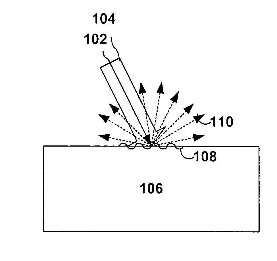
[0028]FIG. 1 depicts two incoming laser beams that generate and detect laser ultrasonic displacements. Laser beam 102 generates ultrasound while illumination laser be...


PUM


Abstract

The present invention provides a compact optical probe assembly that measures ultrasound in materials. The probe uses angle-terminated optical fiber to direct illumination laser light at the surface of a remote target. Ultrasonic displacements at the surface scatter the illumination laser light. Angle-terminated optical fibers collect phase modulated light and direct the phase modulated light to an optical processor to produce a signal representative of the ultrasonic surface displacements. The probe may also incorporate angle-terminated optical fibers to direct generation laser light to the surface of a remote target to generate ultrasonic surface displacements. Optional shared beam forming element(s) may optically act on the illumination laser and collected phase modulated light.

Description

CROSS-REFERENCE TO RELATED APPLICATION [0001] This application is related to and is incorporated herein by reference in its entirety to U.S. patent application Ser. No. 10 / 142,178 entitled “System and Method for Controlling Wafer Temperature”, filed on May 9, 2002, which is a continuation-in-part of and claims priority to 09 / 416,399 entitled Method and Apparatus for Detecting Ultrasonic Surface Displacements Using Post Collection Optical Amplification” to Thomas E. Drake filed on Oct. 12, 1999, which claims priority to U.S. Provisional Patent Application No. 60 / 091,229 filed on Jun. 30, 1998.TECHNICAL FIELD OF THE INVENTION [0002] The present invention relates generally to the generation and detection of ultrasound in materials using lasers, and more particularly, to a system and method that significantly reduces the size of probe for laser ultrasound detection. BACKGROUND OF THE INVENTION [0003] In recent years, the use of advanced composite structures has experienced tremendous gr...

Claims


Application Information

Patent Timeline
IPC IPC(8): G01B11/14
CPCG01N21/1702G01N21/474G01N29/2418
Inventor DUBOIS, MARCDRAKE, THOMAS E. JR.FOMITCHOV, PAVEL
Owner LOCKHEED MARTIN CORP
Why Eureka
Try Eureka