
Multi-station disk finishing apparatus and method

a technology of multi-station disks and finishing apparatuses, applied in grinding drives, cleaning equipments, manufacturing tools, etc., can solve the problems of increased equipment maintenance costs, large capital outlay for equipment and factory floor space, additional time delays, etc., and achieve the effect of easy adaptation

Inactive Publication Date: 2006-06-22
XYRATEX TECH LTD
View PDF12 Cites 32 Cited by
  • Summary
  • Abstract
  • Description
  • Claims
  • Application Information

AI Technical Summary

Benefits of technology

[0016] Although the description herein is, by way of example only, with respect to an abrasive tape texturing unit and texturing process involving fixed or slurry borne abrasive tape that is advanced step-wise between opposed pinch rollers defining a texturing nip into which disks are sequentially introduced for texturing, it should be understood that the inventive system, sub-assembly MSU unit, system controller, and method of finishing are each equally useful for all types of aggressive or abrasive cleaning applications, or post lube, buff / wipe applications to improve the quality of the media surface prior to pre-sputter cleaning, or post-sputter burnishing and glide certification of the disks. Thus the term “finishing” broadly covers all aspects of media disk surface preparation to improve the quality of disk-type memory media.
[0069] Those skilled in this art will appreciate that the inventive system has a wide range of process applications to which it can be easily adapted in the disk finishing industry.

Problems solved by technology

This in turn requires a large capital outlay for equipment and factory floor space, as well as increased equipment maintenance costs.
There are additional time delays in transferring the disk to the next, downstream process, the finer level abrasive tape station for the second stage (fine grit) texturing.

Method used


Image

  • Multi-station disk finishing apparatus and method
  • Multi-station disk finishing apparatus and method
  • Multi-station disk finishing apparatus and method

Examples


Embodiment Construction

[0080] The following detailed description illustrates the invention by way of example, not by way of limitation of the scope, equivalents or principles of the invention. This description will clearly enable one skilled in the art to make and use the invention, and describes several embodiments, adaptations, variations, alternatives and uses of the invention, including what is presently believed to be the best modes of carrying out the invention.

[0081] In this regard, the invention is illustrated in the several figures described above, and is of sufficient complexity that the many parts, interrelationships, and sub-combinations thereof simply cannot be fully illustrated in a single patent-type drawing. For clarity and conciseness, several of the drawings show in schematic, or omit, parts that are not essential in that drawing to a description of a particular feature, aspect or principle of the invention being disclosed. Thus, the best mode embodiment of one feature may be shown in o...


PUM

PropertyMeasurementUnit
Fractionaaaaaaaaaa
Fractionaaaaaaaaaa
Timeaaaaaaaaaa

Abstract

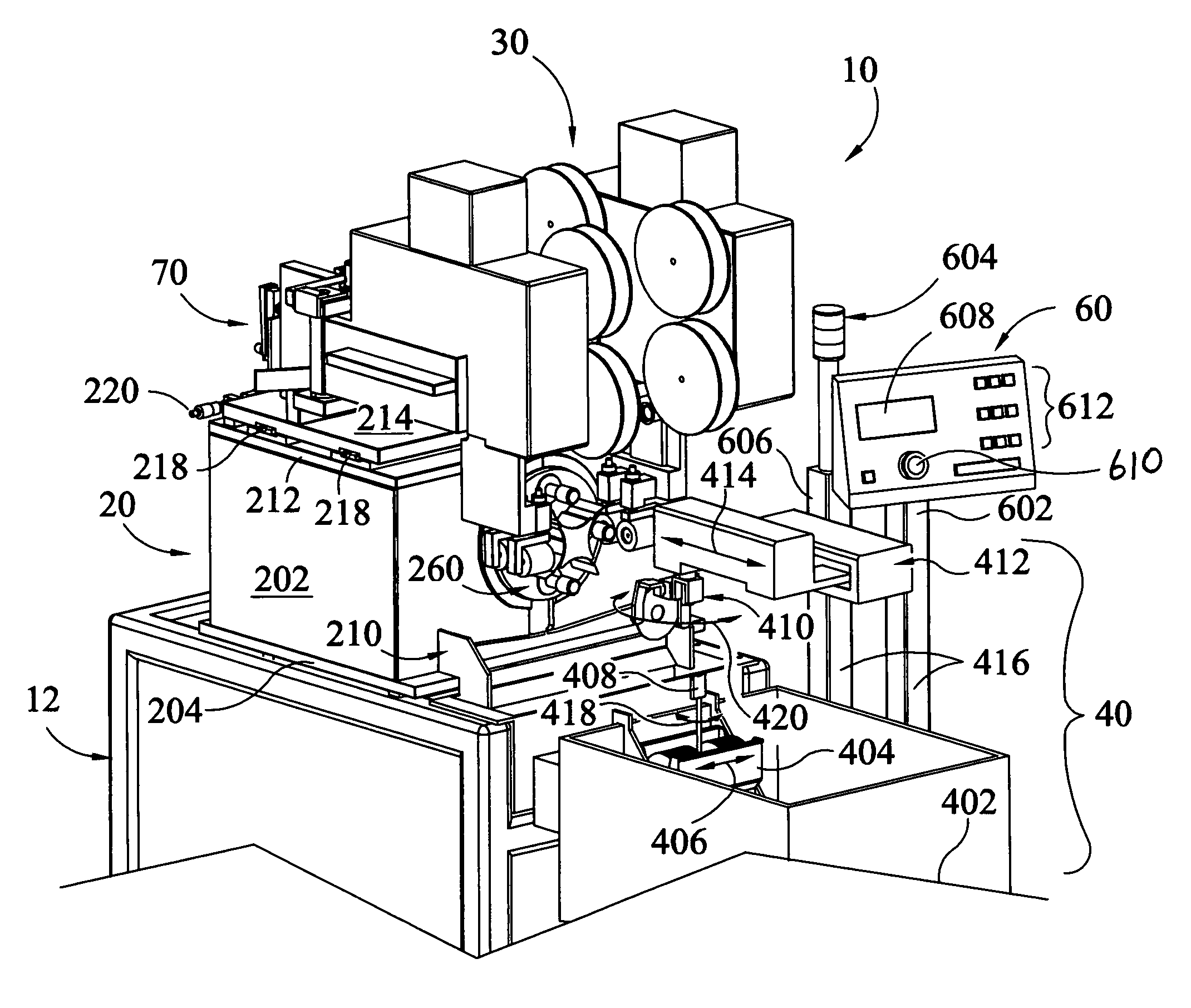
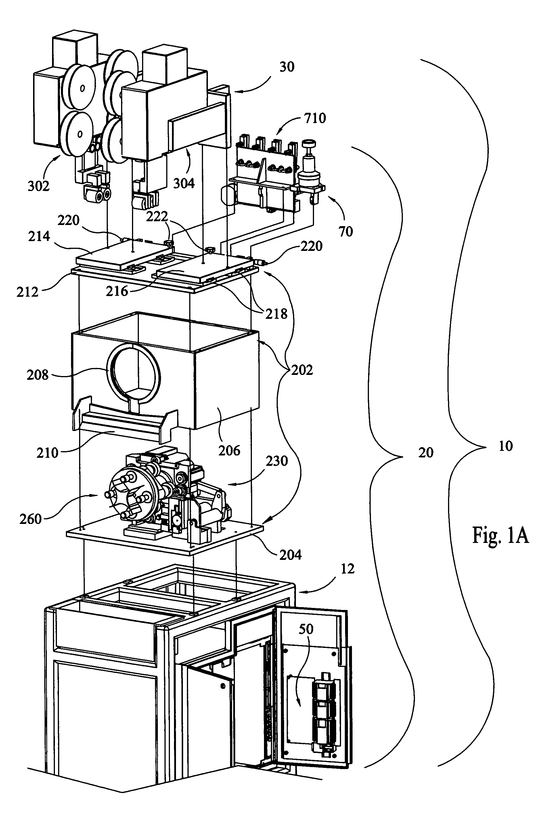
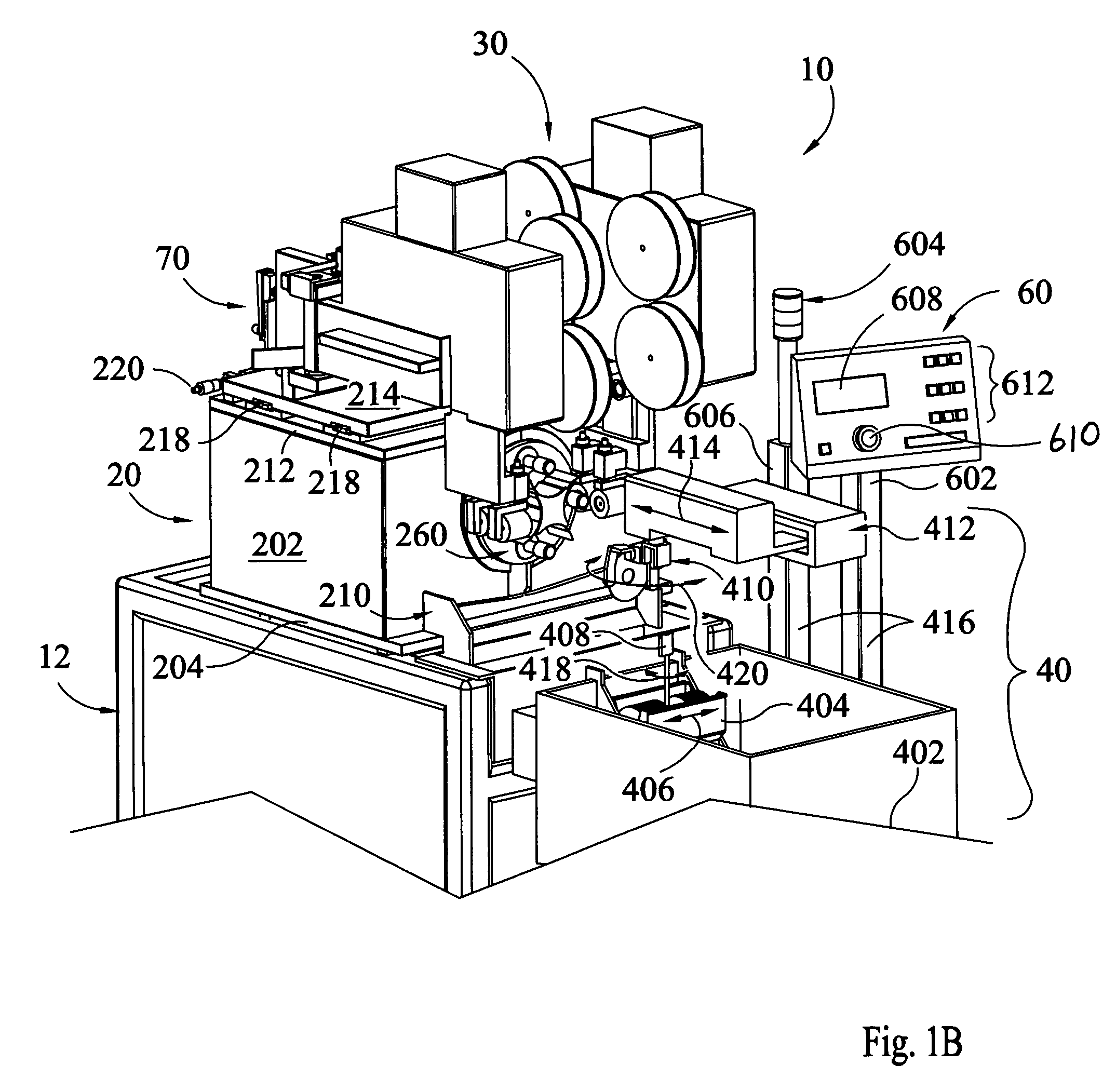
Multi-disk processing system and method of continuous finishing of memory media disks for digital data storage systems in preparation for magnetic memory coating, comprising four main sub-systems: 1) multiple driven spindles mounted on a chassis, at 3, 6, 9 and 12 o'clock positions; 2) finishing tape head units mounted on a base; 3) a robotic handler for loading and unloading disks onto / off at least one of the spindles; and 4) a programmable system controller that controls the sub-system operations and loading / unloading. The tape head sub-system includes its own programmable controller and sensors for control of the finishing tape advance. The multiple spindles and handler rotate relative to each other. In a preferred embodiment, the spindles are mounted on a rotating turntable that also oscillates. Alternately, the spindles are fixed in position and a rotating handler with multiple grippers for simultaneously loading / unloading disks from all spindles at once is used.

Description

CROSS REFERENCE TO RELATED APPLICATIONS [0001] This application is the Regular US Application of prior filed Provisional Applications Ser. No. 60 / 637,067 filed Dec. 17, 2004 by the same inventors under the title MULTI-STATION DISK TEXTURING APPARATUS AND METHOD, and Ser. No. 60 / 701,705 filed Jul. 22, 2005 by the same inventors under the title MULTI-STATION DISK TEXTURING APPARATUS AND METHOD II, the priority of both of which is claimed under 35 US Code §§ 119 and 120, and the entire subject matter of which are hereby incorporated by reference.SPECIFICATION [0002] 1. Copyright Notice under 37 CFR §1.71: [0003] A portion of the disclosure of this patent document contains material which is subject to copyright protection. The copyright owner, Xyratex Technology, Ltd., Havant, UK, has no objecttion to the facsimile reproduction by anyone of the issued patent document or the patent disclosure, as it appears in the US Patent and Trademark Office patent file or records, for the purpose of ...

Claims


Application Information

Patent Timeline
IPC IPC(8): B24B51/00B24B7/30
CPCB24B19/028B24B21/004B24B21/04
Inventor FROST, DAVID T.MCENTEE, JOHNHARBISON, ADAM SEAN
Owner XYRATEX TECH LTD
Learn More