Passive reflection mixer

a reflection mixer and mixer technology, applied in the field of mixers, can solve the problems of low linearity and noise figure, low conversion loss or even gain, and the radio frequency receiver typically receives a growing number of unwanted signals at undesired carrier frequencies, so as to improve the high dynamic range, reduce the level of non-linearity and intermodulation distortion, and improve the effect of low distortion

Active Publication Date: 2006-06-29
SYNERGY MICROWAVE CORP
View PDF3 Cites 44 Cited by
  • Summary
  • Abstract
  • Description
  • Claims
  • Application Information

AI Technical Summary

Benefits of technology

[0036] In another aspect, the present invention is a balanced passive reflection FET mixers that uses a novel configuration and operates with a reduced level of non-linearity and intermodulation distortion. The mixer desirably provides an improved high dynamic range, low distortion double balanced mixer FET or MESFET based, operating in reflection commutating mode, with the application of a DC bias to the drains of the FETs and a high level signal at the gates of the FETs. The mixer also desirably provides low distortion and high linearity at reduced LO signal drive levels, typically +17 dBm, but can be lower or higher, and is not limited by the drive level. The mixer is also useful for both up and down conversion, handling wide frequency bands having overlapping RF and IF frequencies and either LO and RF or LO and IF frequencies without need for filtering. The mixer can also be advantageously made with lumped element transformers at frequencies at or below the L band and with distributed element (microstrip / stripline / suspended stripline) transformers at frequencies above L band. The mixer can also desirably process high signal level inputs with minimal distortion.
[0037] In another aspect, the present invention comprises a relatively low distortion and high dynamic range reflection mode commutating FET double balanced mixer that provides improvement in efficiency and inherent isolation between any two of the three unbalanced ports. The RF and IF ports of the mixer may have overlapping frequencies. In addition, either the LO and RF or LO and IF ports can may also have overlapping frequencies. LO isolation at the non-isolated port is achieved through a filter being low pass, high pass, band pass or band reject. The mixer preferably achieves inherent isolation through a transformer used as a 4-port, 0 / 180 degree phase splitting transformer having two 50 ohms ports (sigma and delta) and two higher impedance ports that are in-phase with the sigma port and 180 degrees out-of-phase with the delta port. The IF and RF output ports are taken from either the sigma or delta ports. The LO signal is fed through a transformer for complementary (0 / 180 degree phase splitter) phase to the gates of the FETs, so that one FET or FET network is conducting (ON) while the other FET or FET network is non-conducting (OFF). A filter may be used at either the sum or sigma ports or both, depending on the isolation desired.
[0038] In another aspect, a parallel LC tuned circuit network provided as part of a slope shaping circuitry improves the rate of energy transfer of the LO drive signal in the given cycle, thereby reducing the non-linearity produced in the mixing cell due to FET ON resistance.
[0039] In another aspect, a series tuned network (as part of the FET structure, presented across the gate and source, formed by the lead inductance and dynamic drive dependent gate-source capacitance) in conjunction with the external parallel LC network minimizes the rise and fall times of the LO input signal.
[0040] In yet another aspect, if the parallel LC-tuned and series tuned networks are used, the LO input signal is enhanced so that the efficiency of the mixer improves significantly, thereby maintaining the 1 dB compression point with reduced LO signal levels.
[0041] In another aspect, the present invention is a field effect transistor mixer preferably comprising a first port where the local oscillator (LO) input signal is split into complementary mode (0 / 180 degrees) by the LO input transformer of transformation ratio 4, and may vary depending upon the bandwidth and level of energy transformation (preferably with impedance transformation of 50 ohms to 200 ohms) and AC coupled through coupling capacitors to the gates of at least two FETs or FET networks so that the FETs or FET network operate in complementary mode. Each of the FETs or FET network preferably have their source grounded and the drains connected to the higher impedance ports of the 0 / 180 degree LO transformer. In accordance with this aspect of the present invention, this circuit configuration amplifies the LO signal and shapes it into a rectangular pulse (preferably 50% duty cycle). The fast rising and falling edges of the shaped LO signal forces the FETs to switch alternatively into saturation (on) pinch-off (off) as reflective commutation (switch) mode. Further in accordance with this aspect of the present invention, the FETs and FET networks may be a dual FET having a gate, source and drain and the FET network can be two or more FETs connected in parallel in such a way that the gates are connected together, further the drains are also preferably connected together and the sources are grounded. Connecting FETs in parallel in this manner to form said networks reduces the inherent drain to source ‘ON’ resistance (rds-ON) in the FETs for lower non-linearities in the FET switches.

Problems solved by technology

The active mixer approach typically yields low conversion loss or even gain, provides a good degree of balance, but often at the expense of modest linearity and the noise figure.
In addition, due to crowding of the usable frequency spectrum and an increasing number of wireless applications, radio frequency receivers typically receive a growing number of unwanted signals at undesired carrier frequencies.
When the unwanted signals are close in frequency to the carrier frequency of the information-bearing signal, a front-end receiver's filter typically cannot remove the unwanted interference signals.
Implementation of these types of mixers is usually challenging.
This mixer is limited to operation in the HF and low VHF region.
This mixer suffers a disadvantage in requiring a large gate voltage in excess of +15 volts to achieve 77 dB of rejection of inter modulation distortion (IMD) products referred to the input signal.
Mixers of the type shown in FIGS. 1A and 1B generally suffer from reduced efficiency due to coupling losses and instability due to the high frequency devices.
The circuit also typically requires a higher operating DC voltage and consumes a higher current.
In addition, isolation of the local oscillator 23 is often poor due to the asymmetry of the circuitry (e.g., sources are grounded and the transformer that typically forms RF-to-IF circuit 25 is connected to load at its center tap).

Method used


Image

  • Passive reflection mixer
  • Passive reflection mixer
  • Passive reflection mixer

Examples


Embodiment Construction

[0064] Even though a mixer works by means of an amplitude-nonlinear behavior in the active device(s), it is generally desired (and expected) that the active device(s) operate as a linear frequency shifter. The degree to which the frequency-shifted signal is attenuated or amplified is an important mixer property. In that regard, the linearity performance of a mixer may be evaluated in terms of its third order intercept point (IP3). In addition, conversion gain can be positive or negative; usually by convention, negative conversion gain is often stated as conversion loss.

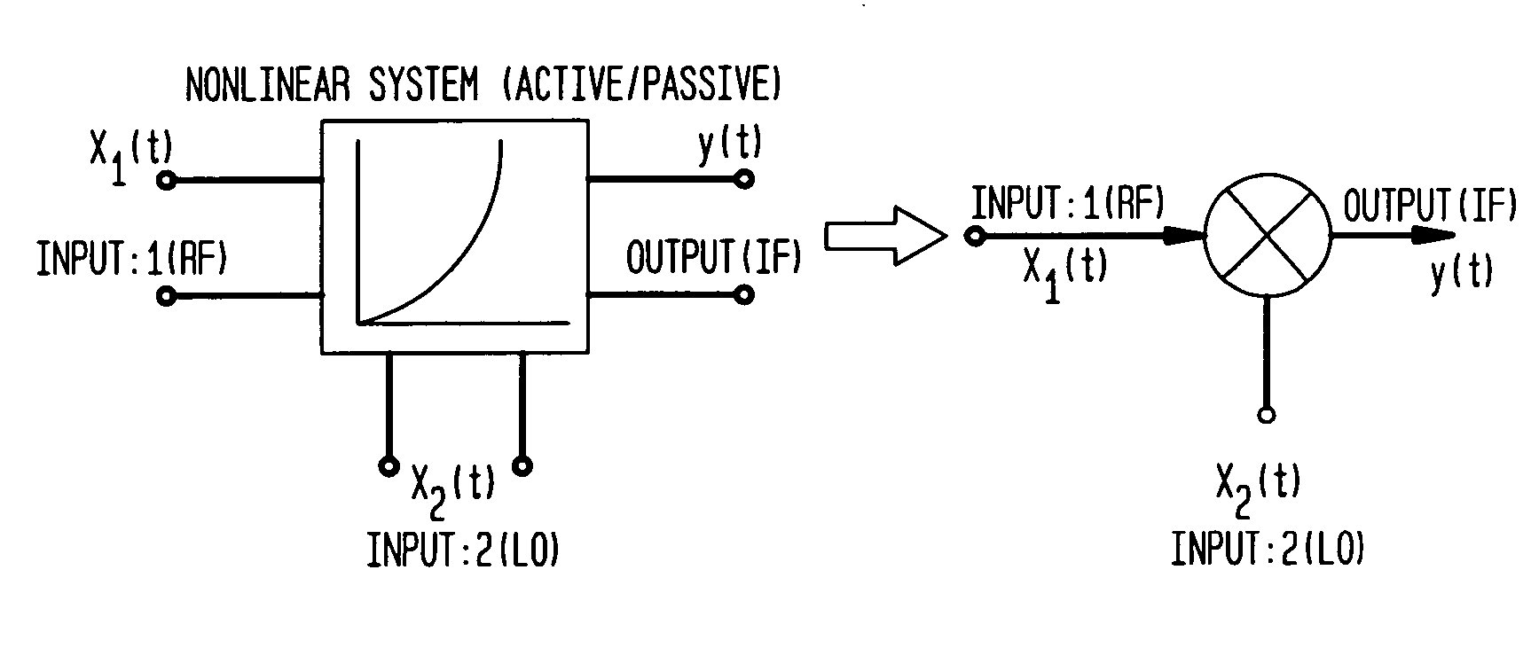
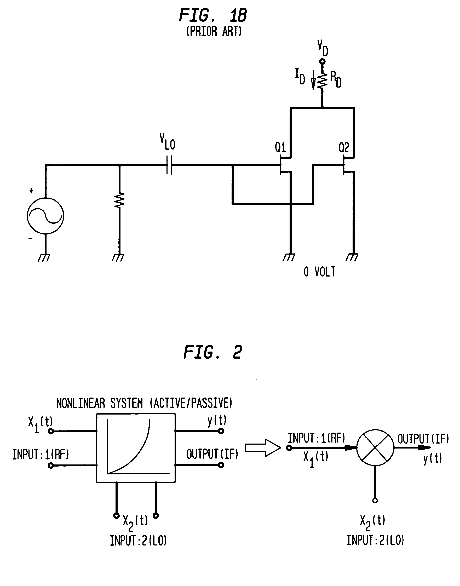
[0065]FIG. 2 shows a model for the system response of a nonlinear network / circuit that is used to establish a relationship between gain compression and an intercept point of a mixer circuit having two inputs, x1(t) and x2(t) in accordance with an aspect of the present invention. In FIG. 2, the system response of the nonlinear network / circuit is illustrated with two inputs, an RF (radio frequency) input and a LO (loca...


PUM


Abstract

In one aspect, a mixer that provides improved isolation between an input oscillator and a mixing cell. In another aspect, a mixer that includes circuitry operative to shape an input signal provided by a local oscillator.

Description

CROSS-REFERENCE TO RELATED APPLICATIONS [0001] This application claims the benefit of the filing date of U.S. Provisional Patent Application Nos. 60 / 622,485 filed Oct. 27, 2004, and 60 / 710,310 filed Aug. 22, 2005, the disclosures of which are hereby incorporated herein by reference.BACKGROUND OF THE INVENTION [0002] The present invention generally relates to mixers. More particularly, the present invention relates to passive reflection mixers including single, double, and triple balanced mixers that employ one or more field effect transistors (FETs). [0003] Mixers typically play an important role in radio frequency (RF) and microwave systems that employ frequency conversion. They are usually used to up-convert signal frequencies for transmission and down-convert received signals to lower intermediate frequencies (IF). Further in that regard, a mixer is generally considered a fundamental building block of a receiver. [0004] Mixers may be broadly classified as either active type or pa...

Claims


Application Information

Patent Timeline
Patent Type & Authority Applications(United States)
IPC IPC(8): H04B1/18H04B1/26
CPCH03D7/1441H03D2200/0023H03D2200/0037H03D2200/0074H03D7/1408H03D7/1458H03D7/1466H03D7/1491H03D2200/0007H03D2200/0088H03D2200/009
Inventor ROHDE, ULRICH L.ALMEIDA, ANTONIOPODDAR, AJAY KUMARAHMED, VASEEMIIKOV, NIKOLAYSCHOEPF, KLAUS JUERGEN
Owner SYNERGY MICROWAVE CORP
Why Eureka
Try Eureka