
Remote access vpn mediation method and mediation device

a remote access vpn and mediation method technology, applied in the field of remote access vpn mediation method and mediation device, can solve the problems of imposing a heavy load not only on the user of the vpn client unit, but also on the vpn administrator, and the burden of user management becomes enormous, and the management of the user becomes a serious burden

Inactive Publication Date: 2006-06-29
NIPPON TELEGRAPH & TELEPHONE CORP
View PDF9 Cites 157 Cited by
  • Summary
  • Abstract
  • Description
  • Claims
  • Application Information

AI Technical Summary

Benefits of technology

[0042] The present invention produces such effects as described below. A first effect resides in that, of pieces of information to be used for implementing a remote-access VPN by an arbitrary tunneling protocol, such as IPsec and L2TP, in an IP network, a global IP address of a VPN client unit, a global IP address of a VPN gateway unit, a private IP address of an arbitrary communication unit in a local area network placed under the control of the VPN gateway unit, and a common key or common secret (hereinafter referred to as mutual authentication information) necessary for mutual authentication for setting up an encrypted tunnel between the VPN client unit and the VPN gateway unit can be shared therebetween with security. The reason for this is secure management of the private IP address in the mediating apparatus and secure distribution of the private IP address and the mutual authentication information.
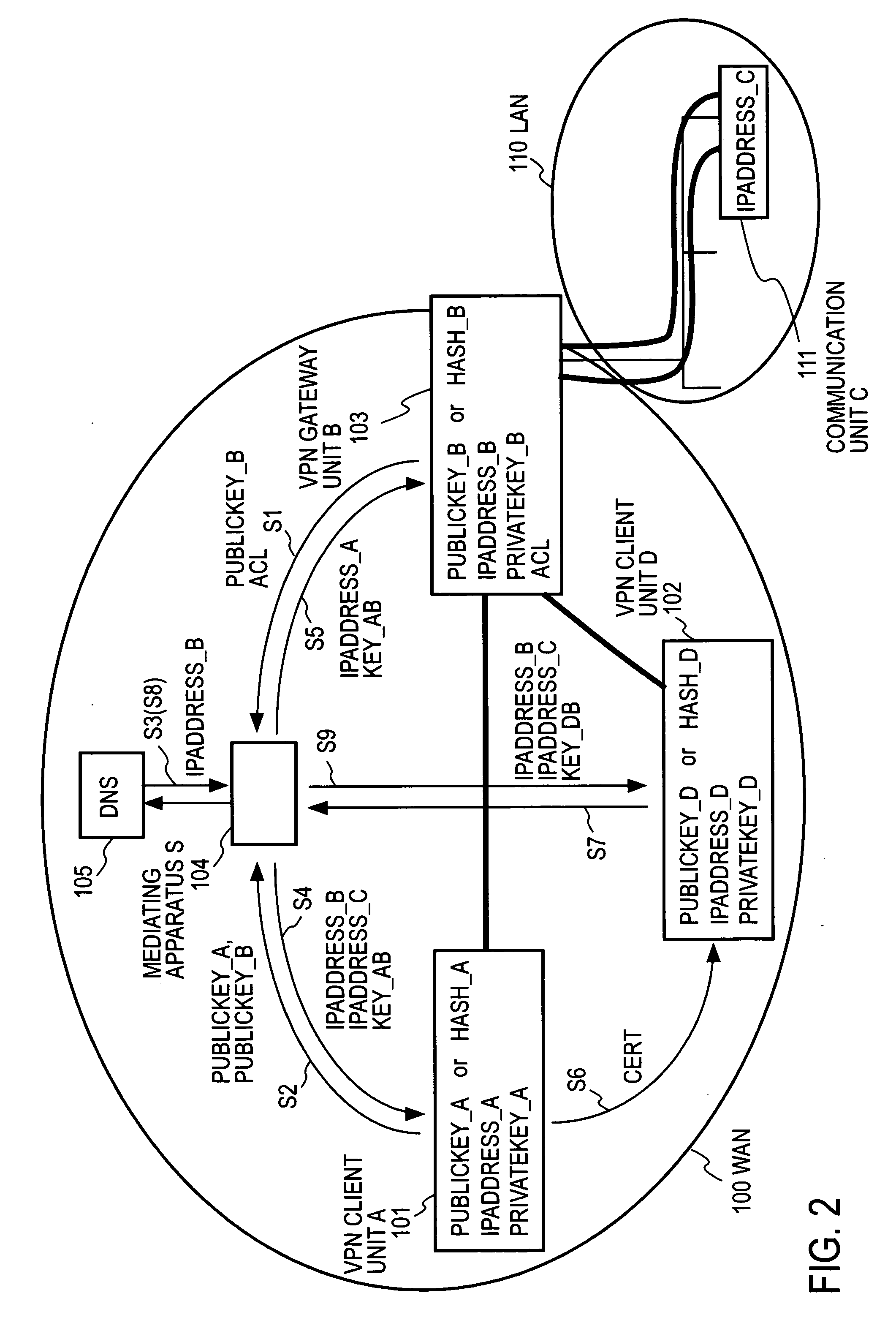
[0043] Specifically speaking, in the case of entry of the private IP address thereinto, the mediating apparatus authenticates the VPN gateway unit and, only when the authentication is successful, encrypts the communication channel, and receives the private IP address over the encrypted communication channel. In the case of retrieval of the private IP address, the mediating apparatus: authenticates the VPN client unit; and, only when the authentication is successful, effects access authorization control by use of the public key of the VPN client unit; and, only when the access authorization control is successful, acquires the global IP address of the VPN gateway unit from the domain name server; encrypts the communication channel between the mediating apparatus and the VPN client unit; sends the global IP address of the VPN gateway unit, the private IP address of the communication unit, and the mutual authentication information to the VPN client unit over the encrypted communication channel; and encrypts the communication channel between the mediating apparatus and the VPN gateway unit; sends the global IP address of the VPN client unit, the mutual authentication information, and attribute information of the VPN client unit to the VPN gateway unit.
[0044] A second effect is to provide means by which communication in the authentication for remote-access VPN can be conducted without leakage of user's personal information to the other party of communication. The reason for this is that in the case of authentication by the PKI scheme, a common key certificate containing personal information is sent to the mediating apparatus for authentication in place of the other party of communication. Another reason resides in that in the case of authentication by the SPLI scheme, the format of any certificate can be so defined as not to contain personal information. On the other hand, the mediating apparatus may be associated with: a function of sending the attribute information accompanying the authentication result to the VPN gateway unit to select VLAN for accommodating the VPN client unit concerned; a function of changing packet filtering setting of the VPN gateway unit concerned; and a function of adding the attribute information concerned to an inverted dictionary of DNS in VPN in the entry corresponding to the private IP address of the VPN client unit.

Problems solved by technology

In general, these settings affect security, and hence they must be done with security and with reliability, which places a heavy load not only on a VPN client unit user but also on a VPN administrator.
And, when users accessible to this VPN change one after another, the burden of user management also becomes tremendous.
Further, when a user accesses two or more VPNs, an authentication method, authentication information, and an IC card or similar authentication device for retaining them may sometimes differ for each VPN to be connected; the management therefor becomes a serious burden.
Further, in the case where the VPN client unit (A) is inside an NAT (Network Address Translation) segment or where it is a portable miniature device of severely limited power requirements, it is not proper to directly establish an encrypted channel for communication with the VPN gateway unit.
However, the method of patent document 1 limits the key distribution range to the local area network and the method of patent document 2 calls for pre-exchanging of the common key between the VPN client unit and the VPN gateway unit, and for these reasons, the management operations become complicated, for example, in the case where the admission and withdrawal of members of a society occur frequently.
And either method does not provide a function of delegating access control to a third party and a function of allowing the VPN client unit to delegate encrypted communication processing to another reliable VPN client unit for access to the VPN gateway to which the VPN client unit is authorized to be connected.
However, this method does not authenticate the VPN client unit that is a receiver—this poses a danger of impersonation attack by masquerading of the IP address and intermediator attack.
Further, no mention is made of how the management unit performs authentication / access control when the VPN client unit issues a request for acquisition of the configuration management information.

Method used


Image

  • Remote access vpn mediation method and mediation device
  • Remote access vpn mediation method and mediation device
  • Remote access vpn mediation method and mediation device

Examples


embodiment 1

[0067] This is an embodiment in which a mediating apparatus authenticates a VPN client unit and a VPN gateway unit by an SPKI (Simple Public Key Infrastructure) scheme, and the VPN client unit issues a certificate for the delegation of authority. This SPKI scheme does not require an authentication station.

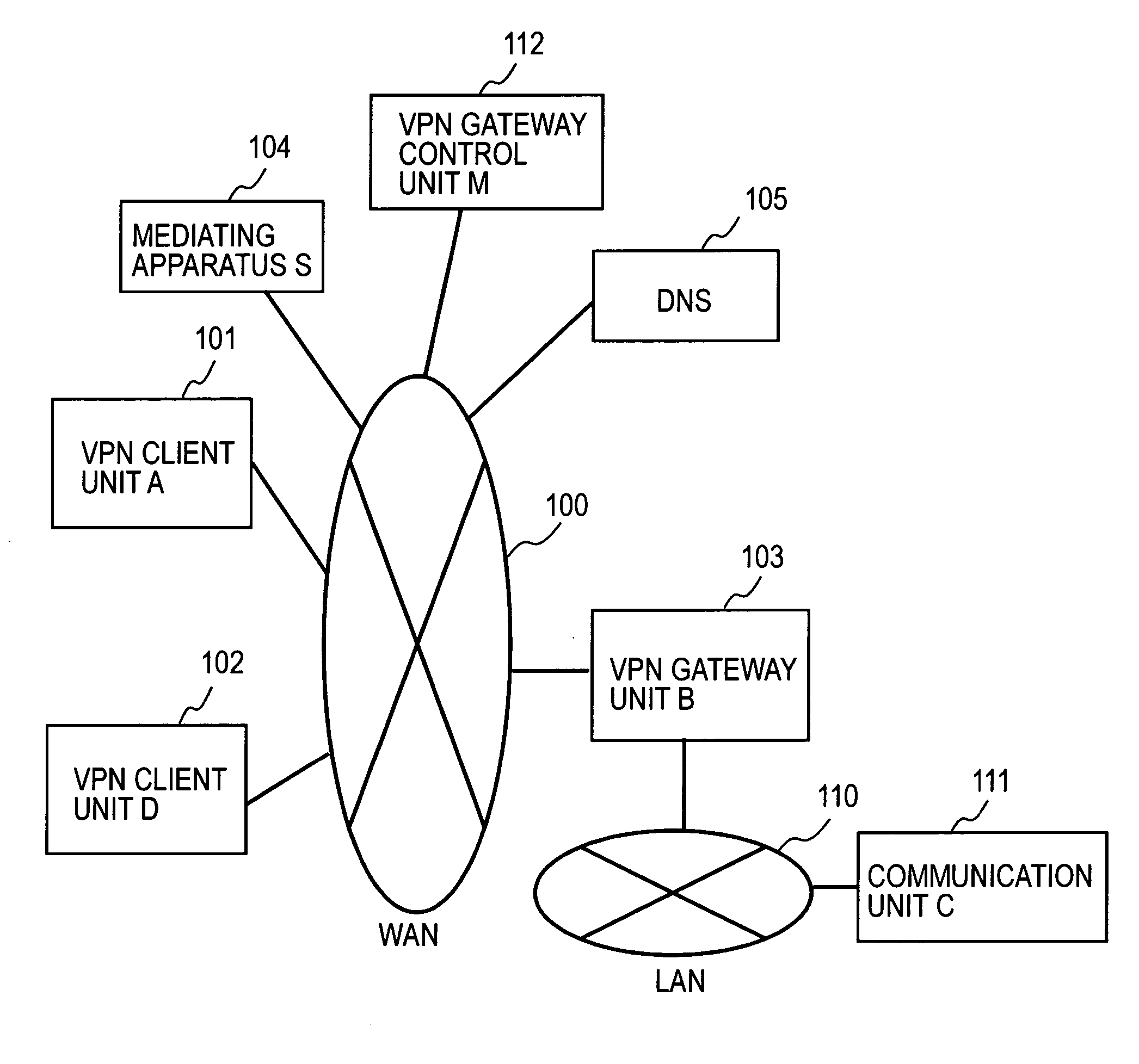
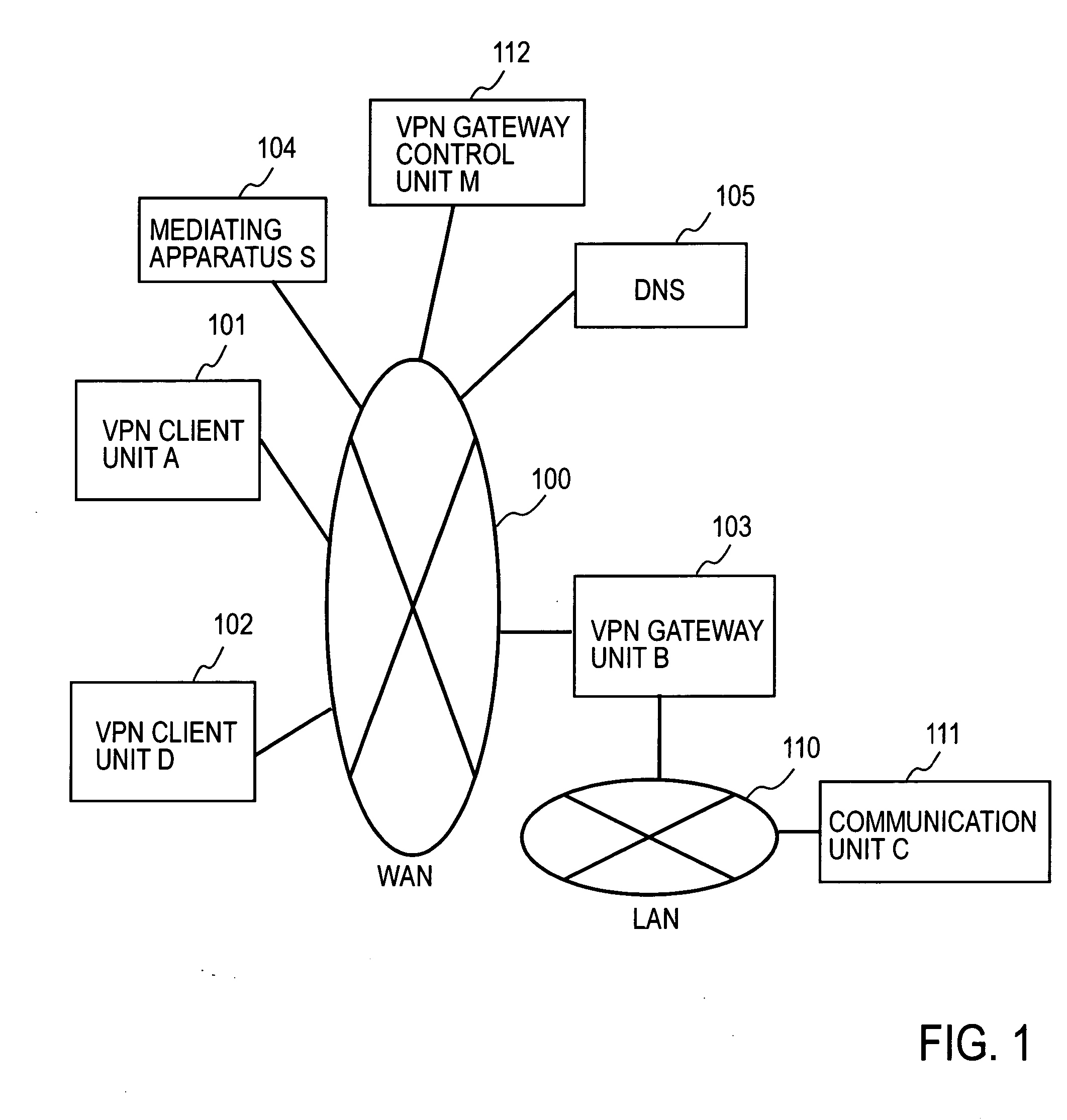
[0068]FIG. 1 illustrates a general system configuration of this embodiment. In FIG. 1 a VPN client unit (A) 101, a VPN client unit (D) 102, a VPN gateway unit (B) 103, a mediating apparatus (S) 104, and a domain name server (DNS) 105 are each connected to a Wide Area Network (WAN) 100 under IP (Internet Protocol). A communication unit (C) 111 is connected to a Local Area Network (LAN) 110 that uses the VPN gateway unit (B) 103 as a gateway unit. On WAN there may also be provided a VPN gateway control unit (M) 112 that has the authority of management of an access control list for the VPN gateway unit (B) 103.

[0069]FIG. 2 is a diagram for explaining the operation of the entire syst...

embodiment 2

[0123] This embodiment further devises the certificate CERT, and provides the certificate CERT in the form of a 0.509-type public key certificate. The basic system configuration of this embodiment is the same as that of Embodiment 1, but an authentication station is required. FIG. 12 illustrates the general system configuration of this embodiment. In FIG. 12 the VPN client unit (A) 101, the VPN gateway unit (B) 103, an authentication station (CA) 106, the domain name server (DNS) 105, and the mediating apparatus (S) 104 are each connected to the network (WAN) 100 under IP (Internet Protocol) control.

[0124]FIG. 13 is a diagram for explaining the operation of the entire system in FIG. 12. The thick lines indicate the remote-access VPN in the IPsec tunnel mode, and the broken lines indicate presentation of the public key certificate CERT to the authentication station (CA) in the authentication in the IKE phase 1. In this embodiment, too, the host name of the VPN client unit (A) 101 is...

embodiment 3

[0159]FIG. 18 illustrates a practical functional configuration of the VPN client unit in Embodiments 1 and 2 described above. The VPN client unit 101 is provided with: a DNS query capture / proxy answer function part 1011 that captures a DNS request from this unit and makes a proxy answer thereto; a mediation-service VPN client function part 1012 that performs a VPN client function of the mediation service of the present invention; and a tunneling protocol function part 1013 for implementing VPN access. Furthermore, there are provided: a mediation service management table 1014 for distinguishing between ordinary DNS queries and mediation services, and for their management; a mediation-service authentication information table 1015 for mutual authentication with a mediation server; and a tunneling / protocol configuration management information table 1016 for encrypted communications with the VPN gateway unit.

[0160] The mediation service management table 1014 has stored therein:

[0161] a...


PUM


Abstract

A mediating apparatus is provided on an IP network, and stores an access control list (ACL) retained in a VPN gateway unit. The mediating apparatus: receives a retrieval request from a VPN client unit; acquires a private IP address of a communication unit by reference to ACL; searches DNS to acquire therefrom an IP address of the VPN gateway unit; generates a common key that is used for authentication between the VPN client unit and the VPN gateway unit and for encrypted communication therebetween; sends the IP address of the VPN gateway unit, the private IP address of the communication unit, and the common key to the VPN client unit; and sends the IP address of the VPN client unit and the common key to the VPN gateway unit.

Description

TECHNICAL FIELD [0001] The present invention relates to techniques by which, of pieces of information for implementation of a remote-access VPN by an arbitrary tunneling protocol, such as IPsec (IPsecurity Protocol) or L2TP (Layer2Tunneling Protocol), a global IP address of a VPN client unit, a global IP address of a VPN gateway unit, and mutual authentication information to be used for authentication between the VPN client unit and the VPN gateway unit are shared in security between them. BACKGROUND ART [0002] A virtual closed network that is built up on the Internet is commonly called a Virtual Private Network (hereinafter abbreviated as VPN). The VPN is built using such a tunneling protocol as IPsec, L2TP or the like, and it is used for accessing a resource in a local area network (LAN) from a moving client via the Internet, or for interconnecting multiple physically dispersed local area networks via the Internet. In the case of authorizing a remote user to access a remote-access...

Claims


Application Information

Patent Timeline
IPC IPC(8): G06F15/16G06F17/00G06F9/00H04L9/08H04L12/46H04L12/70H04L29/06
CPCH04L12/4641H04L63/0272H04L63/101H04L9/006
Inventor HISADA, YUSUKETSURUOKA, YUKIOONO, SATOSHI
Owner NIPPON TELEGRAPH & TELEPHONE CORP
Learn More