
Metal halide lamp

a technology of metal halide lamps and halide lamps, which is applied in the direction of discharge tubes/lamp details, discharge tubes luminescnet screens, gas-filled discharge tubes, etc., can solve the problems of short distance between the inner wall of the arc tube and the arc, arc tube to a high temperature, and arc tube to a large thermal shock, etc., to achieve favorable luminous flux maintenance factor and low reactivity

Inactive Publication Date: 2006-07-06
PANASONIC CORP
View PDF5 Cites 0 Cited by
  • Summary
  • Abstract
  • Description
  • Claims
  • Application Information

AI Technical Summary

Benefits of technology

"The present invention provides a metal halide lamp with an arc tube that includes a main tube part made of polycrystalline alumina ceramic, which has enhanced resistance against thermal shocks and a high luminous efficiency. The arc tube also includes a pair of thin tube parts that connect from the main tube part and are sealed by respective sealing members with the electrode structures inserted therein. The construction of the arc tube satisfies various requirements, such as tube wall loading, distance between electrodes, inner diameter of the main tube part, crystal grain diameter of the polycrystalline alumina ceramic, and magnesium oxide content. The use of polycrystalline alumina ceramic with low reactivity with the enclosure and containing magnesium oxide of low concentration results in a long life for the metal halide lamp. The main tube part made of polycrystalline alumina ceramic with low reactivity with the enclosure has a high transmittance, which further enhances the efficiency of the metal halide lamp."

Problems solved by technology

However, in such a metal halide lamp having a slim shape, the distance between the inner wall of the arc tube and the arc becomes short, subjecting the arc tube to a high temperature.
As a result, the arc tube will be subjected to a large thermal shock.
A conventional arc tube having a comparatively large inner diameter will not be subjected to such a high heat during the lamp's illumination, and so it is very rare that a crack is caused due to a thermal shock.
However if an arc tube is made to be slim for the purpose of providing a high-efficiency lamp, it is apt to crack incident to an extreme thermal shock explained above, thereby shortening a lamp life.

Method used


Image

  • Metal halide lamp
  • Metal halide lamp
  • Metal halide lamp

Examples


modification example

8. Modification Example

[0073] So far, the present invention has been described based on the embodiment. Needless to say, the present invention should not be limited to the concrete example shown in the above embodiment, and includes the following modification examples, for example.

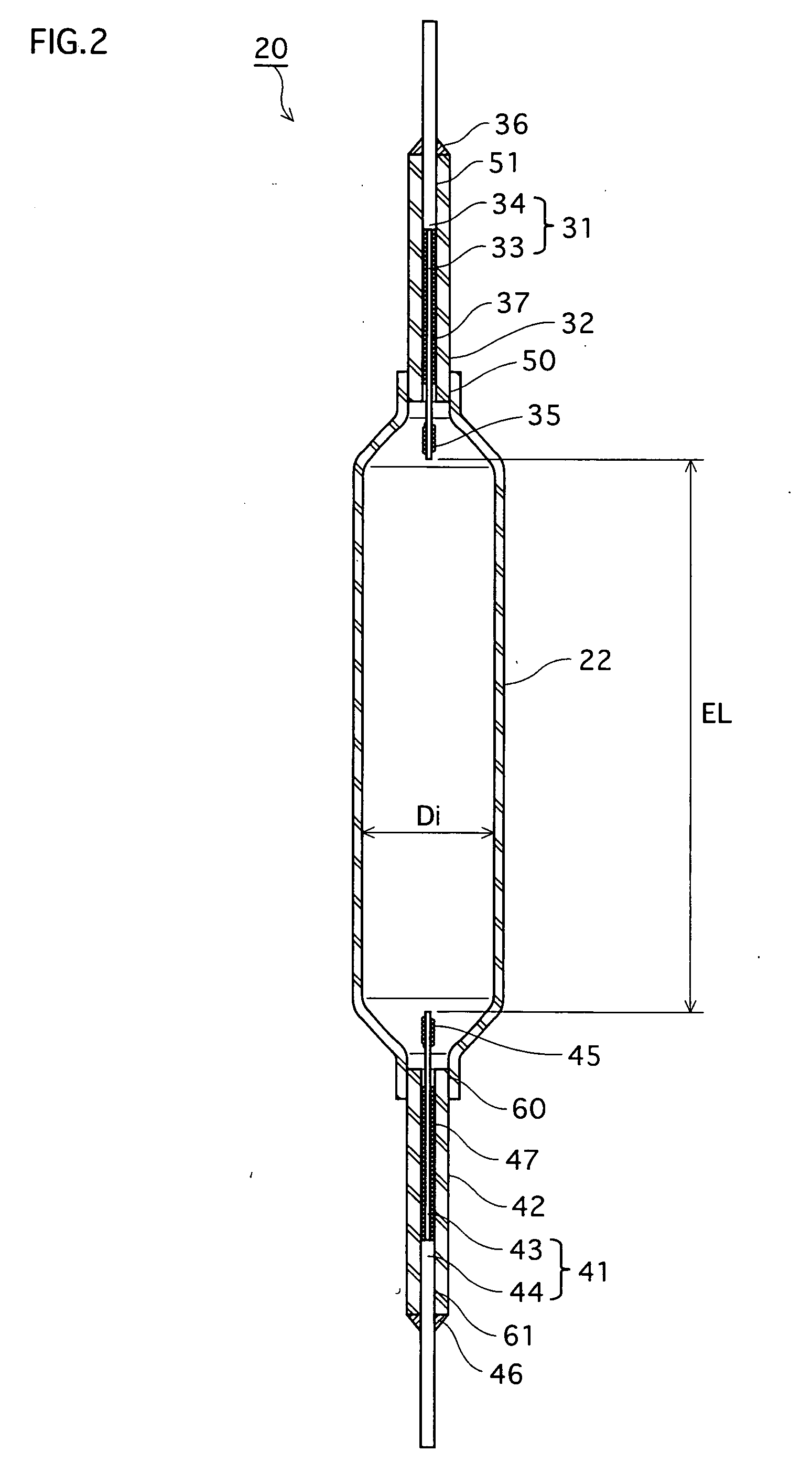
[0074] In the above description, alumina has a small crystal grain diameter throughout the main tube part 22. However, a structure in which the crystal grain diameter is locally reduced is also possible. For example, in the case where the inner diameter Di of the main tube part 22 is 5 mm, sometimes the arc will be bent. This means that the central portion will be intensively heated. In this case, occurrence of a crack is restrained if the alumina's crystal grain diameter is adjusted to be 5.0 μm or below exclusively at the central portion of the main tube part 22 and its vicinity.

[0075] Furthermore, in the above description, a focus is given to the crystal grain diameter of alumina used as a material of...


PUM


Abstract

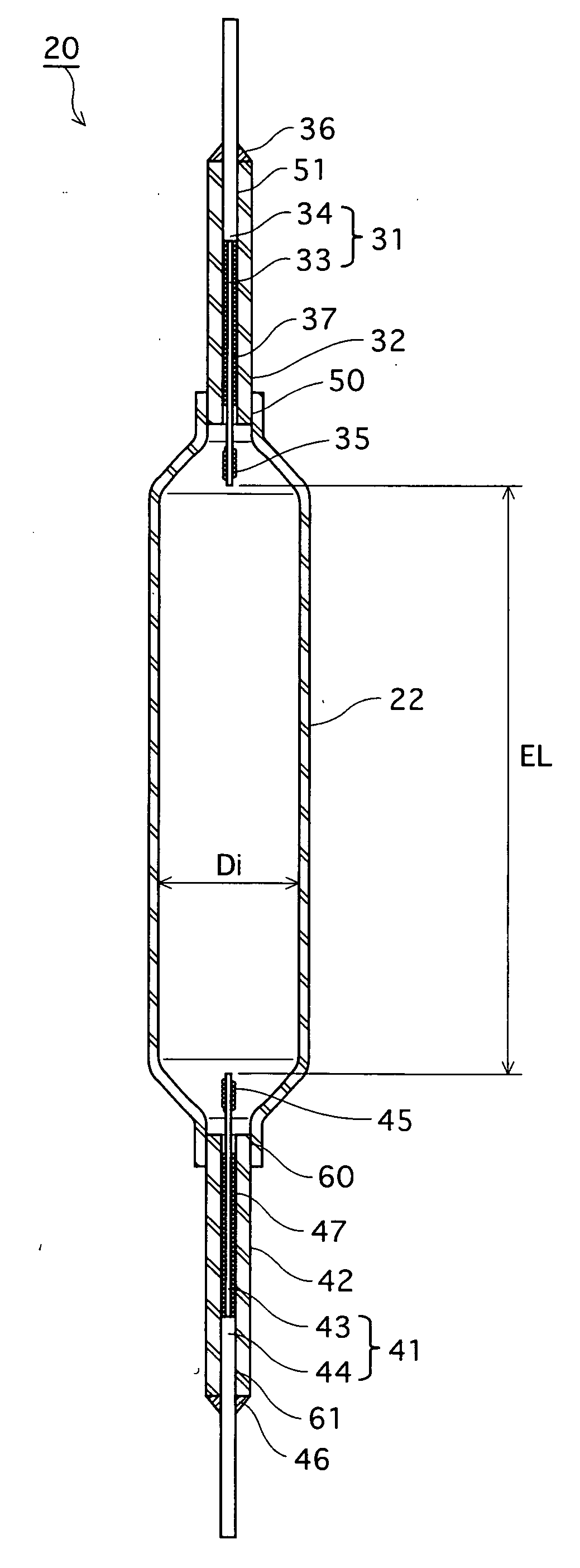
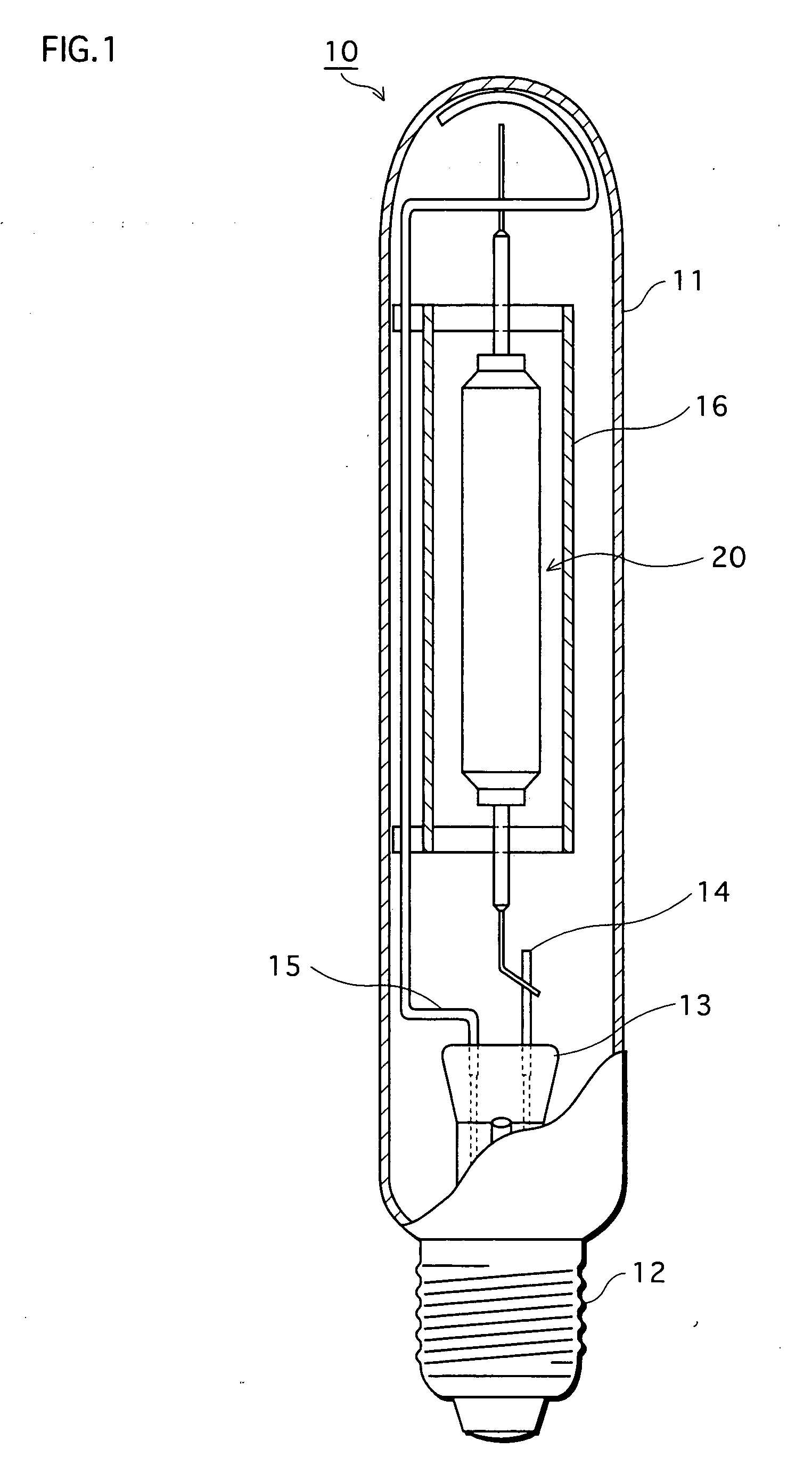
A metal halide lamp has an arc tube that includes: a pair of electrode structures, each of which has an electrode at a tip; a main tube part made of polycrystalline alumina ceramic, and containing a discharge space in which the electrodes of the electrode structures are located to oppose each other; and a pair of thin tube parts that connect from the main tube part and are sealed by respective sealing members with the electrode structures inserted therein, where 20≦WL≦50, EL / Di≧2.0, and 0.5≦G≦5.0 are satisfied where tube wall loading of the arc tube is WL(W / cm2), a distance between the electrodes is EL(mm), an inner diameter of the main tube part is Di (mm), and a crystal grain diameter of the polycrystalline alumina ceramic is G(μm)

Description

FIELD OF INVENTION [0001] The present invention relates to a metal halide lamp. BACKGROUND ART [0002] Metal halide lamps having been developed in recent years are widely used for interior lighting especially in commercial establishments such as in shops. [0003] Conventionally, most arc tubes of metal halide lamps were made of quartz. In recent years, however, arc tubes made of ceramic materials have been actively developed. Quartz arc tubes are heat resistant up to about 1000° C., whereas ceramic arc tubes are heat resistant up to about 1200° C. or more. Therefore if a metal halide lamp has a ceramic arc tube, it has higher tube wall loading, and achieves high efficiency and high color rendering. A common ceramic material is polycrystalline alumina ceramic (Al2O3) (hereinafter occasionally referred to as “alumina”) whose transmittance is high as 90% or more, and so is instrumental in improving lamp efficiency. [0004] Meanwhile, a Japanese Laid-open patent application No. 2002-536786...

Claims


Application Information

Patent Timeline
Patent Type & Authority Applications(United States)
IPC IPC(8): H01J17/16H01J61/30H01J17/20H01J61/34H01J61/82H01J61/88
CPCH01J61/302H01J61/827
Inventor TAKEUCHI, NOBUYOSHINISHIURA, YOSHIHARU
Owner PANASONIC CORP
Learn More