Metallized heat resistant material with thermal barrier

a heat-resistance material and thermal barrier technology, applied in the direction of synthesizing resin layered products, record information storage, packaging, etc., can solve the problems of high cost of transporting styrofoam-based packaging that requires a large storage volume, and low supply of packaging materials

Inactive Publication Date: 2006-07-06
CROWLEY SHAWN KELLY
View PDF24 Cites 27 Cited by
  • Summary
  • Abstract
  • Description
  • Claims
  • Application Information

AI Technical Summary

Benefits of technology

[0046] The apparatus of the present invention provides a layered film apparatus that may be processed to form bags, pouches, totes, or other p...

Problems solved by technology

This need stems from: the high costs associated with transporting Styrofoam-based packaging that requires a large storage volume.
Also in dealing with the many unanticipated events of the fishing year and...

Method used


Image

  • Metallized heat resistant material with thermal barrier
  • Metallized heat resistant material with thermal barrier
  • Metallized heat resistant material with thermal barrier

Examples


Embodiment Construction

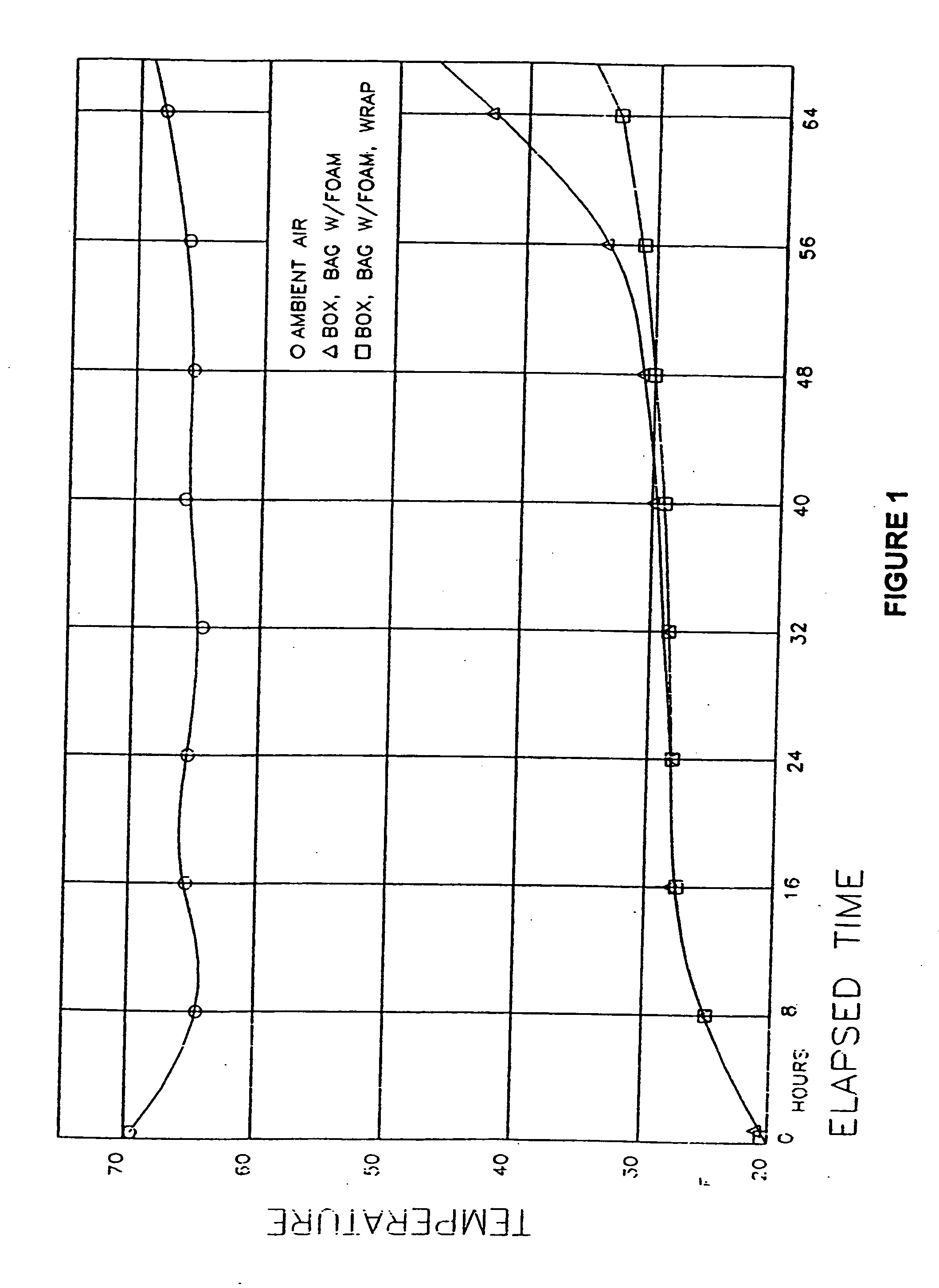
[0064] The graph of FIG. 1 shows the results of using the metallized heat resistant material of the present invention as a bag which may be sealed, both with and without a plastic bubblewrap layer. The increase in time for which foodstuffs may remain frozen through the use of the metallized heat resistant material of the present invention with bubblewrap is shown by the lower trace versus the metallized heat resistant material of the present invention without bubblewrap in the upper trace. As can be seen, even the bag without the bubblewrap layer kept the product cold for a significant period of time.

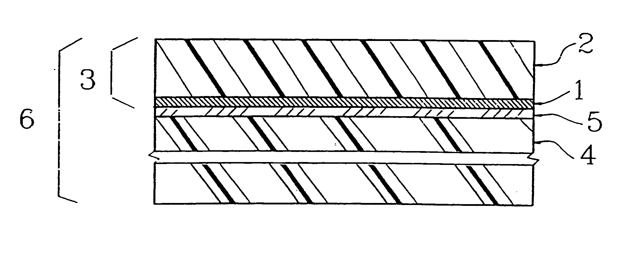
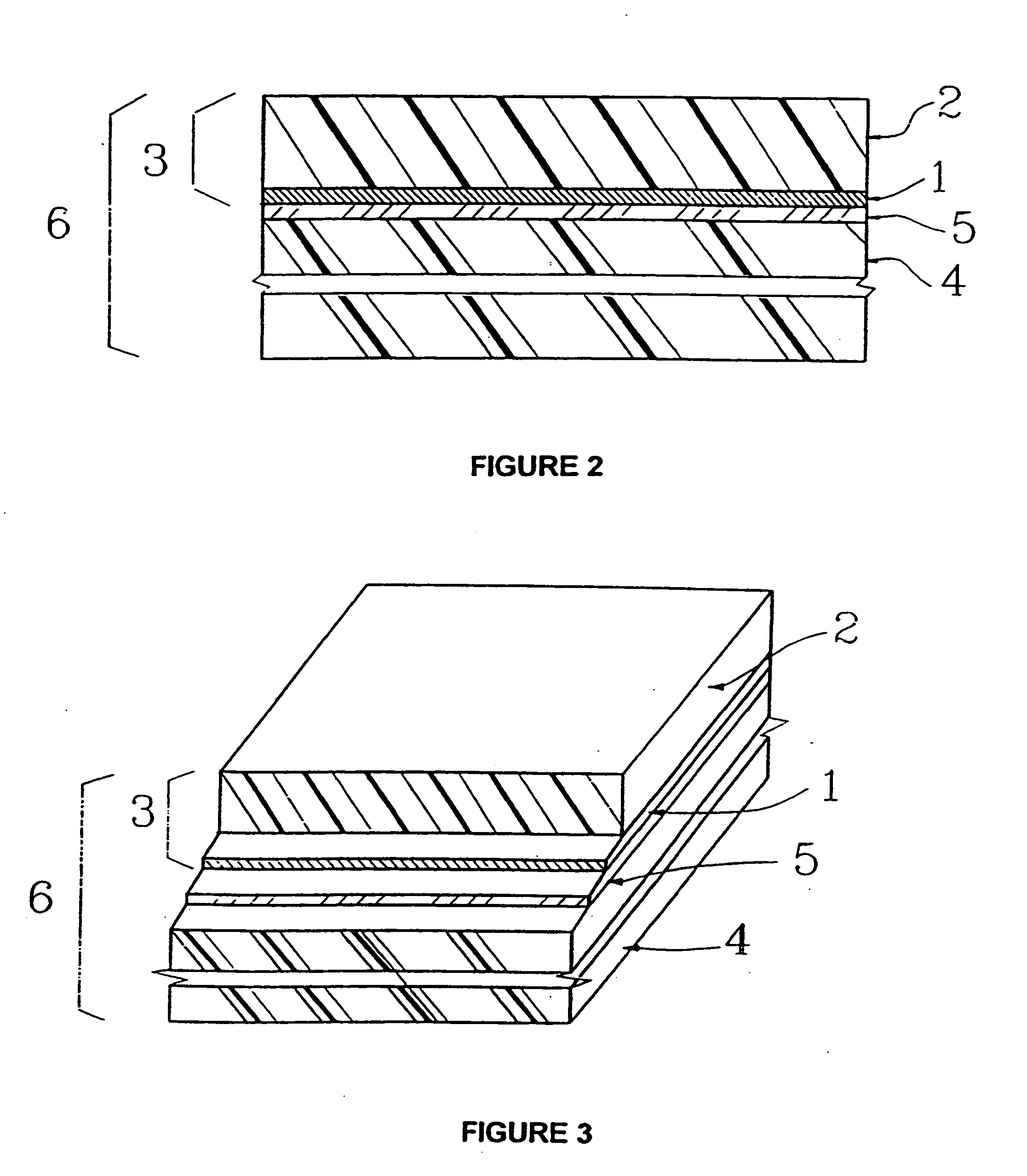
[0065]FIGS. 2 and 3 illustrate a metallized heat resistant material 6 which is assembled as a lamination of two film layers. The first layer and upper surface 3 is the primary laminate which is a film composed of vapor deposited aluminum 1 on a polyester film 2. The polyester film 2 is acceptable for a production thickness of 0.00010 inch to 0.00100 inch (0.0254 to 0.254 mm), but more ...


PUM

PropertyMeasurementUnit
Fractionaaaaaaaaaa
Thicknessaaaaaaaaaa
Thicknessaaaaaaaaaa

Abstract

A laminated metallized film apparatus being fabricated through the use of roll-to-roll lamination machinery (e.g. using a gravure cylinder) which through the use of various combinations of adhesive, pressure, and temperature bonds various materials and substrates together, producing a thermal radiative and insulative barrier to impinging multiple heat sources in the range of ultra-violet longwave-infrared wavelengths. In applications the laminated metallized film apparatus may be constructed so as to create an insulating bag, pouch, tote, insulative wrap, or radiant reflector sheeting, through use of single or multiple layer films or foams of varying thickness and texture.

Description

CROSS-REFERENCE TO RELATED APPLICATIONS [0001] U.S. Provisional Patent Application Ser. No. 60 / 633,803, filed Dec. 7, 2004, priority of which is hereby claimed, is incorporated by reference. [0002] U.S. Provisional Patent Application Ser. No. 60 / 023,056, filed Aug. 2, 1996, and U.S. Provisional Patent Application Ser. No. 60 / 009,737, filed Jan. 11, 1996, is hereby claimed. Those applications are hereby incorporated by reference. [0003] U.S. patent application Ser. No. 10 / 245,829, filed 17 Sep. 2002, is incorporated herein by reference, as are U.S. patent application Ser. No. 08 / 781,285 and its corresponding PCT application no. PCT / US97 / 00473 (published as WO 97 / 25196 on 17 Jul. 1997), both filed 10 Jan. 1997. However, this is not a continuation or continuation-in-part of any of these patent applications.STATEMENT REGARDING FEDERALLY SPONSORED RESEARCH OR DEVELOPMENT [0004] Not applicable REFERENCE TO A “MICROFICHE APPENDIX”[0005] Not applicable BACKGROUND OF THE INVENTION [0006] 1. ...

Claims


Application Information

Patent Timeline
IPC IPC(8): B32B27/08B32B15/09B32B27/32B32B3/12B32B3/26G11B11/105G11B5/64B32B15/08
CPCB32B5/18Y10T428/265B32B27/065B32B27/08B32B27/32B32B27/36B32B2255/10B32B2255/205B32B2266/025B32B2266/08B32B2307/306B32B2439/46B32B2439/70Y10T428/1334Y10T428/24496Y10T428/26Y10T428/1352B32B7/12Y10T428/249992Y10T428/249982Y10T428/31681Y10T428/24999Y10T428/31938Y10T428/249991Y10T428/249985Y10T428/249953
Inventor CROWLEY, SHAWN KELLY
Owner CROWLEY SHAWN KELLY
Why Eureka
Try Eureka