[0006] It is therefore an object of the present invention to create a method with improved reliability for controlling a safety system in a vehicle that is effective for pedestrians and / or bicyclists.
[0008] The
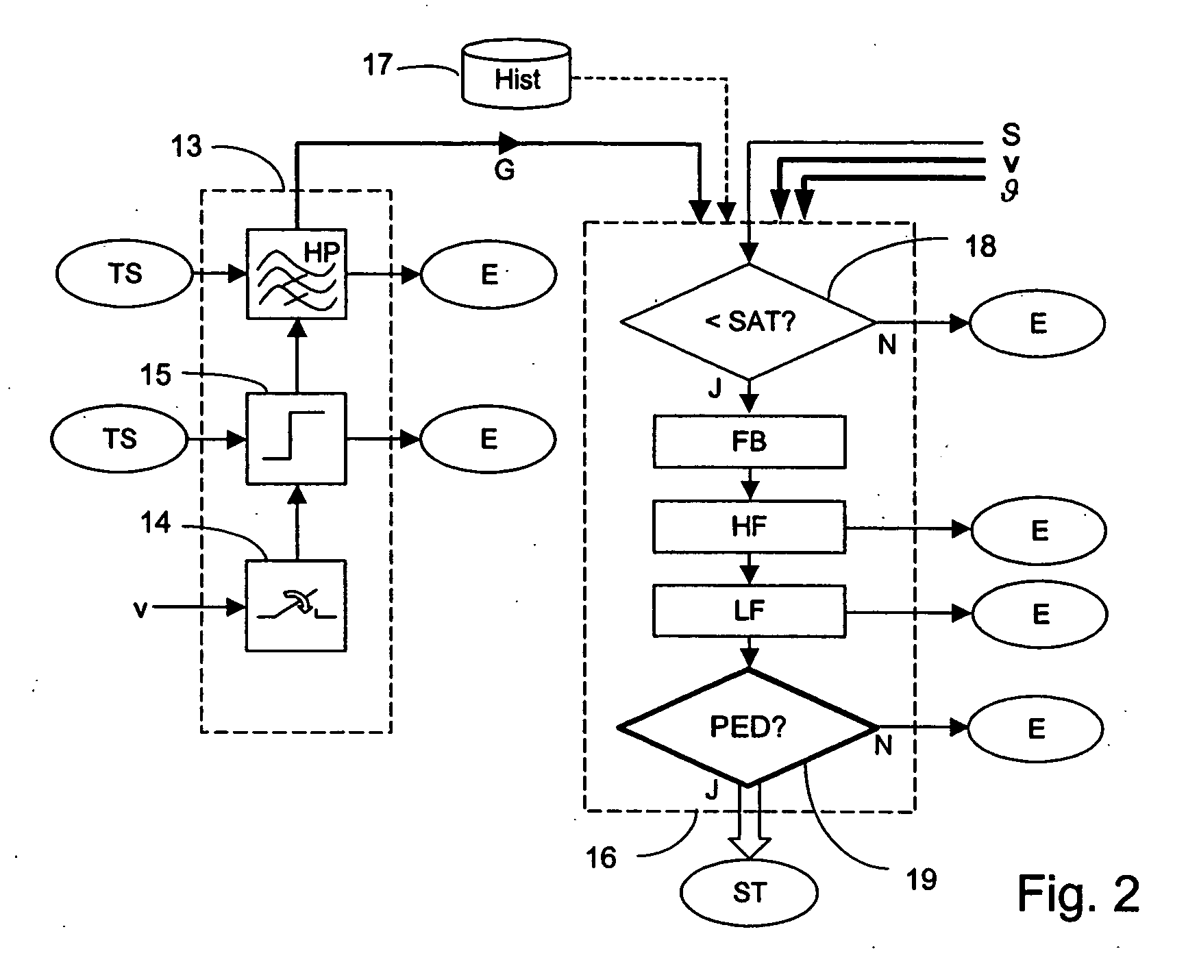
current velocity of the vehicle v and the outside temperature of the vehicle θ are given a special value. In both cases this involves easily measurable parameters, which are also conventionally recorded for other electronic control units in the vehicle. Vehicle velocity v is taken into account in the method of the present invention because there is a surprising influence on the sensor signal spectrum when there is a hard on soft and a soft on soft impact. It has also become known that the elements of a vehicle become less elastic as the outside temperature θ of the vehicle drops, so that a material that is soft under
normal conditions reacts like a progressively harder material as the temperature drops. This is especially true for a soft outside bumper covering that is relatively soft under
normal conditions. Taking at least one of these parameters into account therefore clearly increases the detection reliability of a method according to the present invention.
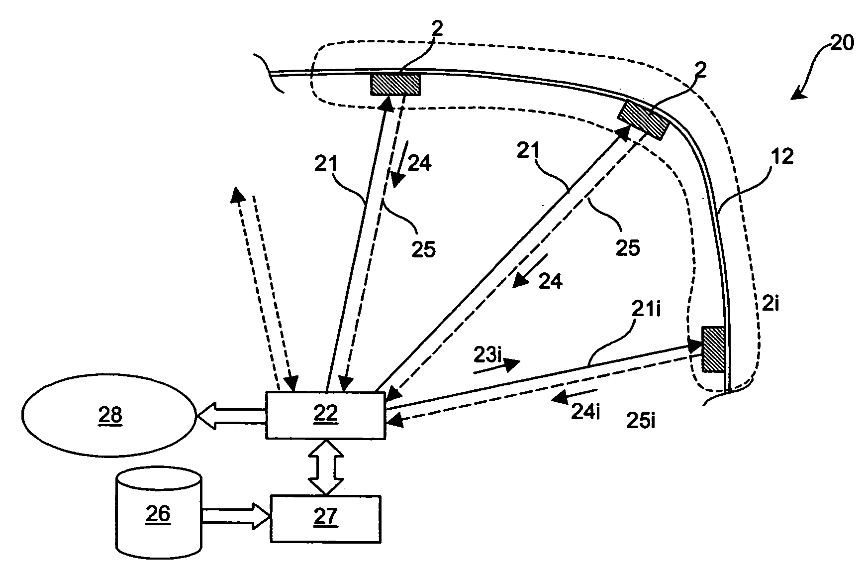
[0010] The materials mentioned above have in common that they can be used as passive sensors, with self-testing also being possible in a simple manner by making use of the reciprocity of piezo-electric materials with external
active control and subsequent evaluation by a central system unit. For this purpose, the sensor element is therefore first controlled as an
actuator, with the mechanical oscillation thus excited again being sensed as an electrical signal if the element is working without interference. This sensing can be performed by the sensor operated exactly as an
actuator just as by at least one adjacently arranged sensor. This makes it possible for each sensor of a
sensor field to be checked and monitored at any time for its operating properties with no additional expense for equipment like signal transmitters, etc.
[0011] In addition to the self-test of a particular sensor, however, a mechanical oscillation can also be imposed on a system to be safeguarded or monitored by the
actuator operation, with an analysis of the oscillation created being subsequently provided by the same element with the properties of this system response being examined in an evaluation unit of the actual safety system. In addition to deformations of the material, cracks and other disturbances can also be detected in this way, especially by a frequency pattern that deviates from this system response. Thus, the present invention provides a method for operating a sensor with a reciprocal
mechanism of action in a safety system, and offers the advantages of reliable self-testing. The present invention also provides the
advantage of
safety testing and
system analysis provided at minor expense and with negligible interference in an overall
mechanical system to be monitored, and with a diagnosis to complete each test. Prior damage of certain parts inside a motor vehicle can thereby be detected at any time and can be taken into account as well during the analysis of a possibly currently occurring accident, since each type of prior damage causes either a
softening of parts of the frame or stiffening but in each case a deviation from unimpaired normal behavior.
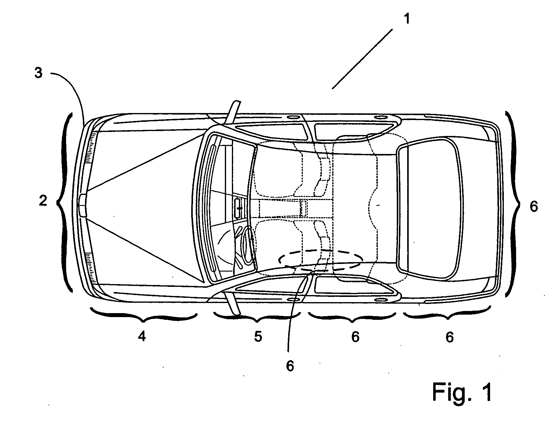
[0014] In the event that non-
harmonic oscillations develop, as, for example, in the case of impact with a
foreign object or a
pedestrian, precise identification of a particular event and location of its position are possible via the particular sensor elements. Accordingly, an evaluation of the intensity of the particular output signals is performed, which can be linked with a measurement of signal-
transit time. Taken together, these rapidly give a reliable picture of an impact with a conclusion about the location or locations of the impact and the type of object or
human being with which there has been an impact.
[0016] A method according to the invention is therefore also distinguished in its developments in that the use of robust, overload-resistant, cost-effective sensors that can be safely used over a wide temperature range and are capable of self-diagnosis, allows rapid and very reliable recognition of accidents with a
pedestrian or bicyclist.

