
Metal foil tube and method and apparatus for production thereof

a metal foil tube and tube body technology, applied in the direction of electrographic process, manufacturing tools, instruments, etc., can solve the problems of reducing strength, reducing hardness (hv) to about half, and roughness (rz) about 3 m, so as to achieve the effect of elongating the shape and surface roughness

Inactive Publication Date: 2006-07-13
INADA KOKI +6
View PDF0 Cites 30 Cited by
  • Summary
  • Abstract
  • Description
  • Claims
  • Application Information

AI Technical Summary

Benefits of technology

[0086] (48) A method of production of a metal foil tube as set forth in any one of (32) to (47), characterized in that a ratio of the inside diameter of the metal foil tube to the thickness of the metal foil sheet is 1/500 or less.
[0087] (49) A method of production of a metal foil tube as set forth in any one of (32) to (48), characterized by inserting a metal core into the metal foil tube and cold working the tube by sedging, split roller rolling, drawing, spinning, or a combination of these methods to reduce the thickness, s...

Problems solved by technology

However, with a thin metal tube obtained by working a tube blank (thick metal tube) fabricated by press working, laser welding, plasma welding, etc. by thinning technology, the structure of the weld zone melts once due to the laser welding or plasma welding, its hardness (Hv) falls to about half, and the strength also declines.
For example, when spinning to work it by about 90%, there are the problems that the surface roughness (Rz) is about 3 μm and surface flaws occur along with the thinning.
Therefore, there is the problem that a sufficient rotational precision is hard to obtain due to the vibration or uneven rotation having a detrimental effect on the desired sharp full color image.
Further, in these thinning technologies, the process of production is complicated and the production cost tends to rise.
With a non-thermoplastic or heat curing polyimide or other resin, shaping is not possible.
Further, compared with joining metal, when joining resin, the joint strength is weak and imparting long term durability is difficult.
In particular, when used at a high temperature, heat embrittlement is seen in which the load applied to the joint zone causes separation at the joint zone etc.
Therefore, this is not suitable for a toner roll etc.
There was therefore the problem of swelling production costs.
Further, the inventors were not satisfied with the novel metal foil tube obtained by the novel method of production and production apparatus and engaged in intensive efforts to make further improvements.
Further, the fixing roll of a printer sometimes becomes flawed at the surface due to the entry of foreign matter.
Once flawed, this has a detrimental effect on the later printing results.

Method used


Image

  • Metal foil tube and method and apparatus for production thereof
  • Metal foil tube and method and apparatus for production thereof
  • Metal foil tube and method and apparatus for production thereof

Examples


example 1

[0259] Stainless steel foils made of SUS410L (11% Cr-0.02% C) were rolled to thicknesses of 40 μm while suitably controlling the rolled surface roughnesses to give surface roughnesses Rz of 1.5 μm and 0.8 μm. The rolled materials were cut to 94.3 mmL×250 mmW. The foils having the two types of surface roughnesses were wrapped around 30 mmφ copper alloy tools and joined at the 100 μm overlap parts by mash seam welding. At this time, the vicinities of the joint zones of both tubes ((a) tube having a surface roughness Rz of 1.5 μm and (b) tube having a surface roughness Rz of 0.8 μm) were cut out, buried, and polished. In both cases, it was confirmed that the hardness of the matrix part was, in Hv, around 270, while the hardness of the joint zone was, in Hv, around 230. The two polishing samples were etched and examined for metal structure. As a result, in both cases, there was no melted and solidified phase at the joint zone, the joint surface was a solid phase in state, and a low carb...

example 2

[0260] Annealed foils having surface roughnesses Rz of 1.0 μm and 0.5 μm, made of SUS316L (16% Cr-12% Ni-2% Mo), and having thicknesses of 30 μm were slit to 60 mm widths. These were wrapped in spirals around the above 30 mmφ copper alloy electrode rods. At this time as well, the foil with the surface roughness Rz of 1.0 μm and the foil with the surface roughness Rz of 0.5 μm were adjusted so that the overlap between sections of the foil became 100 μm. Further, it is possible to rotate the electrode rod and make it slide to the left and right and to roll over the overlap part by another copper alloy or other rolling electrode roller and pass current with the electrode rod for mash seam welding. The same procedure was followed as in Example 1 to investigate the hardnesses of the vicinities of the joint zones of the two tubes ((c) tube having a surface roughness Rz of 1.0 μm and (d) tube having a surface roughness Rz of 0.5 μm). As a result, in both tubes, the matrix part had a hardne...

example 3

[0262] Completely annealed foils having surface roughnesses Rz of 0.3 μm and 0.8 μm, made of SUS304 (18% Cr-8% Ni), and having thicknesses of 50 μm were used by the same method as in Example 1 to prepare two types of foil tubes. Note that the stainless steel foils were annealed in an Ar—H2 atmosphere. The nitrogen concentrations of the surfaces were 1.2%. In both cases ((e) tube having surface roughness Rz of 0.3 μm and (f) tube having surface roughness Rz of 0.8 μm), the joint zones had thicknesses of 75 μm. The inside and outside surfaces were polished to 60 μm. In this case, with both tubes, the hardness of the matrix part was about, in terms of Hv, 178, while that of the joint zone was, in Hv, around 220. The same procedure was followed as in Example 1 for a fatigue test. The result was that both tubes (e) and (f) withstood the fatigue test for 1 million cycles or more.


PUM

PropertyMeasurementUnit
Temperatureaaaaaaaaaa
Fractionaaaaaaaaaa
Fractionaaaaaaaaaa

Abstract

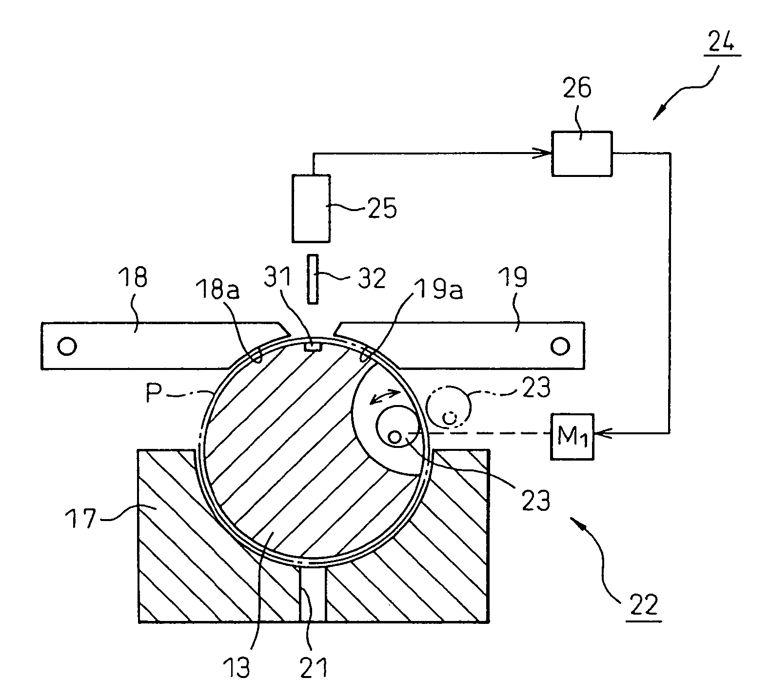
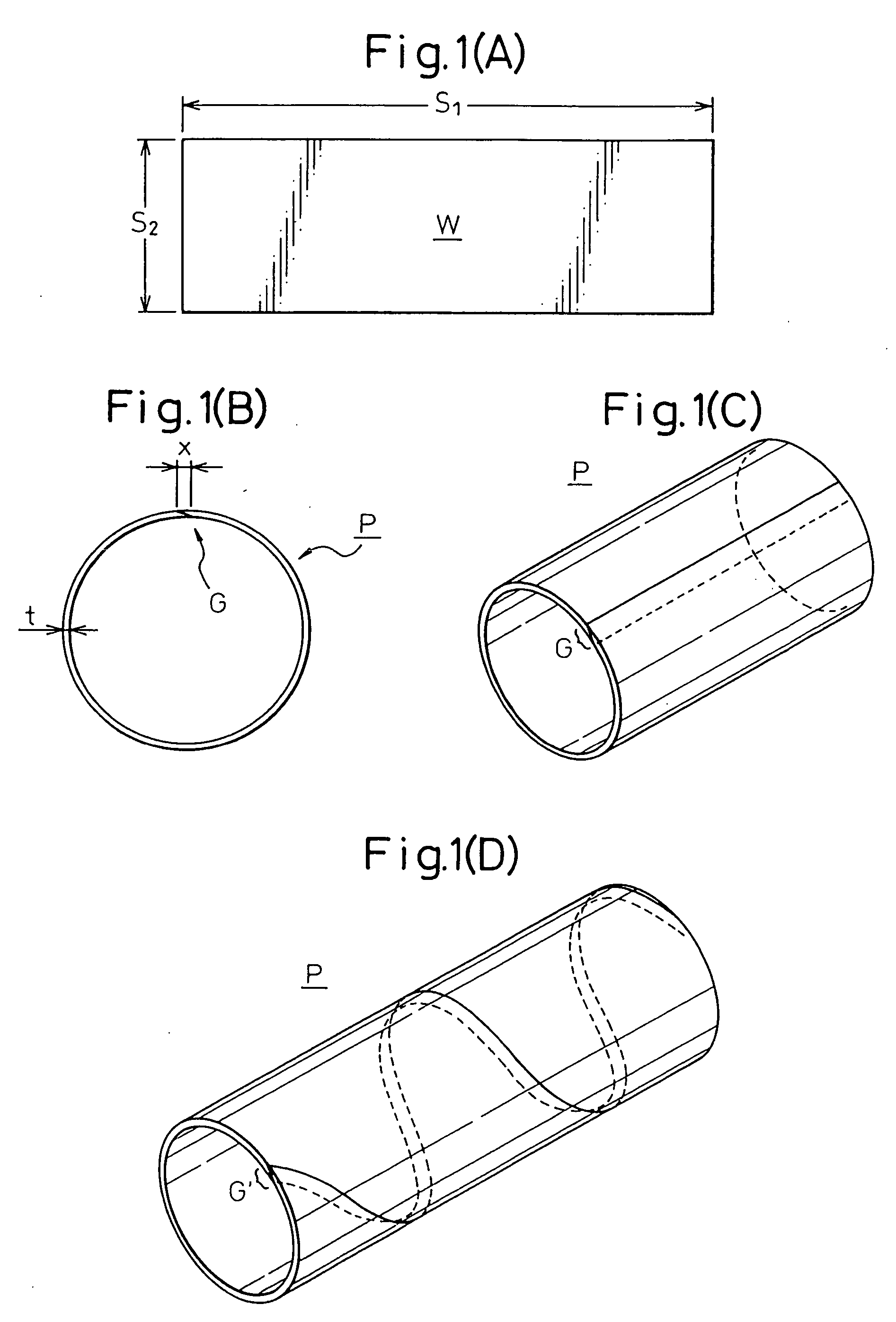
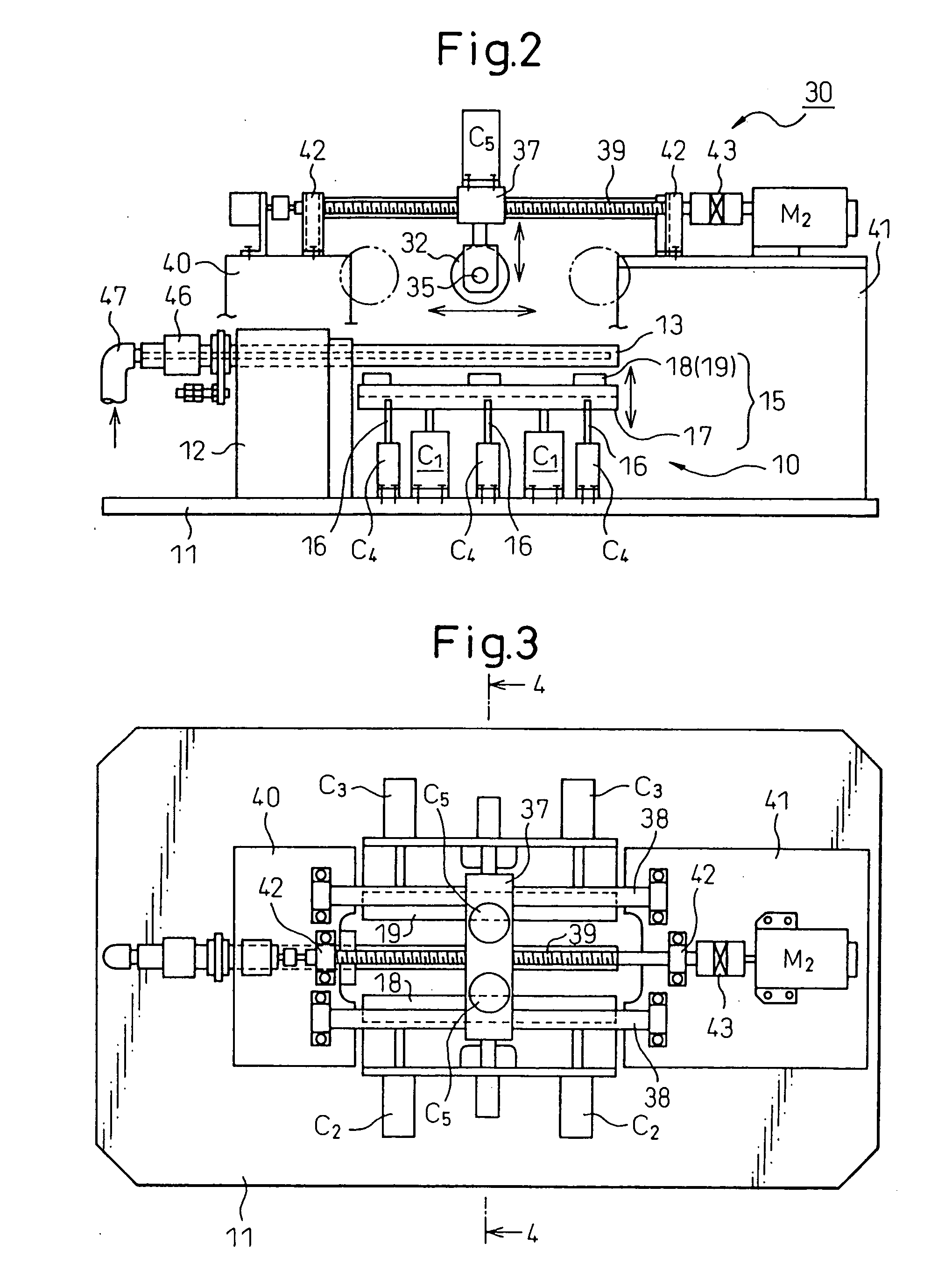
The present invention provides a metal foil tube with a thickness of 10 to 100 μm and a method and apparatus of production of the metal foil tube enabling even an extremely thin metal foil to be reliably finished into a tube, that is, a metal foil tube comprised of a metal foil sheet W with a thickness t of 10 to 100 μm joined by welding, the method of production of the metal foil tube shaping the metal foil sheet W to form an overlap part G, then welding the facing sides and finishing the weld zone part flat.

Description

TECHNICAL FIELD [0001] The present invention relates to a novel metal foil tube and a method of production and production apparatus for the same. More particular, it relates to a novel metal foil tube suitable for use for a copier, facsimile, etc. of an electronic photo printer, laser beam printer (LBP), toner roll, development roll, fixing roll, etc. and a method of production and production apparatus for the same. BACKGROUND ART [0002] In current electronic photo printers, laser beam printers (LBP), copiers, facsimiles, and other image forming devices, a photosensitive drum is exposed by an image signal, a developer forms a toner image, the toner image formed on this photosensitive drum is transferred to paper, and a fixer is used to fix it by heat for output. In such an image forming process, the photosensitive drum, toner roll, development roll, pressing roll, fixing roll, and various other roll members are used. Normally, these roll members are formed into tubular or cylindrica...

Claims


Application Information

Patent Timeline
IPC IPC(8): B21D39/03B21D39/00B21C37/08B21D5/01B21D33/00B21D51/10B23K11/06B23K11/08B23K11/087B23K11/16B23K103/04C22C38/08C22C38/34C22C38/42C22C38/44C22C38/58
CPCB21C37/0815B21D5/015B21D33/00B23K11/084B23K11/0873C22C38/34Y10T29/49927C22C38/44C22C38/58G03G2215/0634G03G2215/20Y10T29/49826C22C38/42G03G15/0818G03G15/2057B23K11/06B21C37/08
Inventor INADA, KOKIIWAMI, KAZUTOSHIIMAI, ATSUHIKOKOBAYASHI, HIROKITAKAHASHI, YASUOYAMANAKA, MUKIOSAITO, TOHRU
Owner INADA KOKI
Learn More