
System for catalytic combustion

a technology of catalytic combustion and combustion system, which is applied in the direction of combustion using catalytic materials, combustion types, turbine/propulsion fuel heating, etc., can solve the problems of large amount of uncombusted methane passing through the turbine and into the atmosphere, inefficient use of methane, damage to the environment,

Active Publication Date: 2006-07-13
COMMONWEALTH SCI & IND RES ORG
View PDF14 Cites 44 Cited by
  • Summary
  • Abstract
  • Description
  • Claims
  • Application Information

AI Technical Summary

Benefits of technology

[0071] Preferably, the catalytic combustor contains a catalyst having a high activity and a high reaction surface area.
[0087] Preferably, the turbine does not require cooling air from the outlet stream of the compressor to cool the inlet scroll and the first stage of the turbine.

Problems solved by technology

However, if the air contains methane, this results in a large amount of uncombusted methane passing through the turbine and into the atmosphere.
Not only is this an inefficient use of the methane, but it is also damaging to the environment and a waste of energy.
However, previous attempts of this have run into several difficulties; having to inject support fuel (eg. natural gas) into the catalytic combustor to maintain efficient combustion, not being able to efficiently handle gas streams with less than 2 mole % methane, having to excessively raise the pressure of the gas stream thereby reducing the overall electrical output of the system, and having difficulty in controlling the gas temperature at the outlet of the combustor at a constant value below 800° C. so that cooling at the inlet of the turbine is not required, and having problems in handling the waste gas, which by its nature has a fluctuating composition.

Method used


Image

  • System for catalytic combustion
  • System for catalytic combustion

Examples


Embodiment Construction

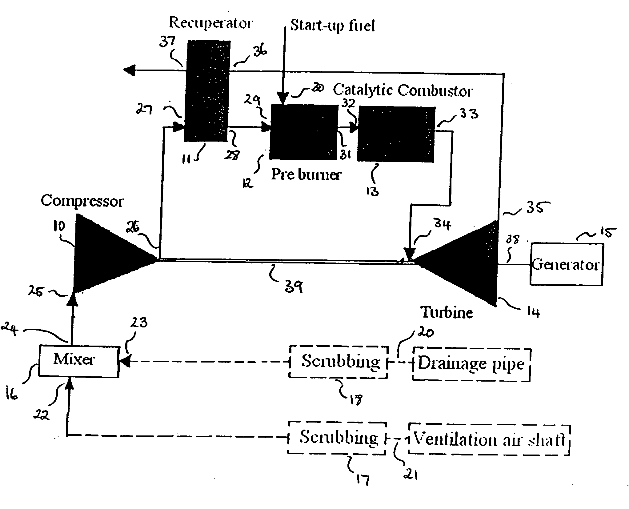
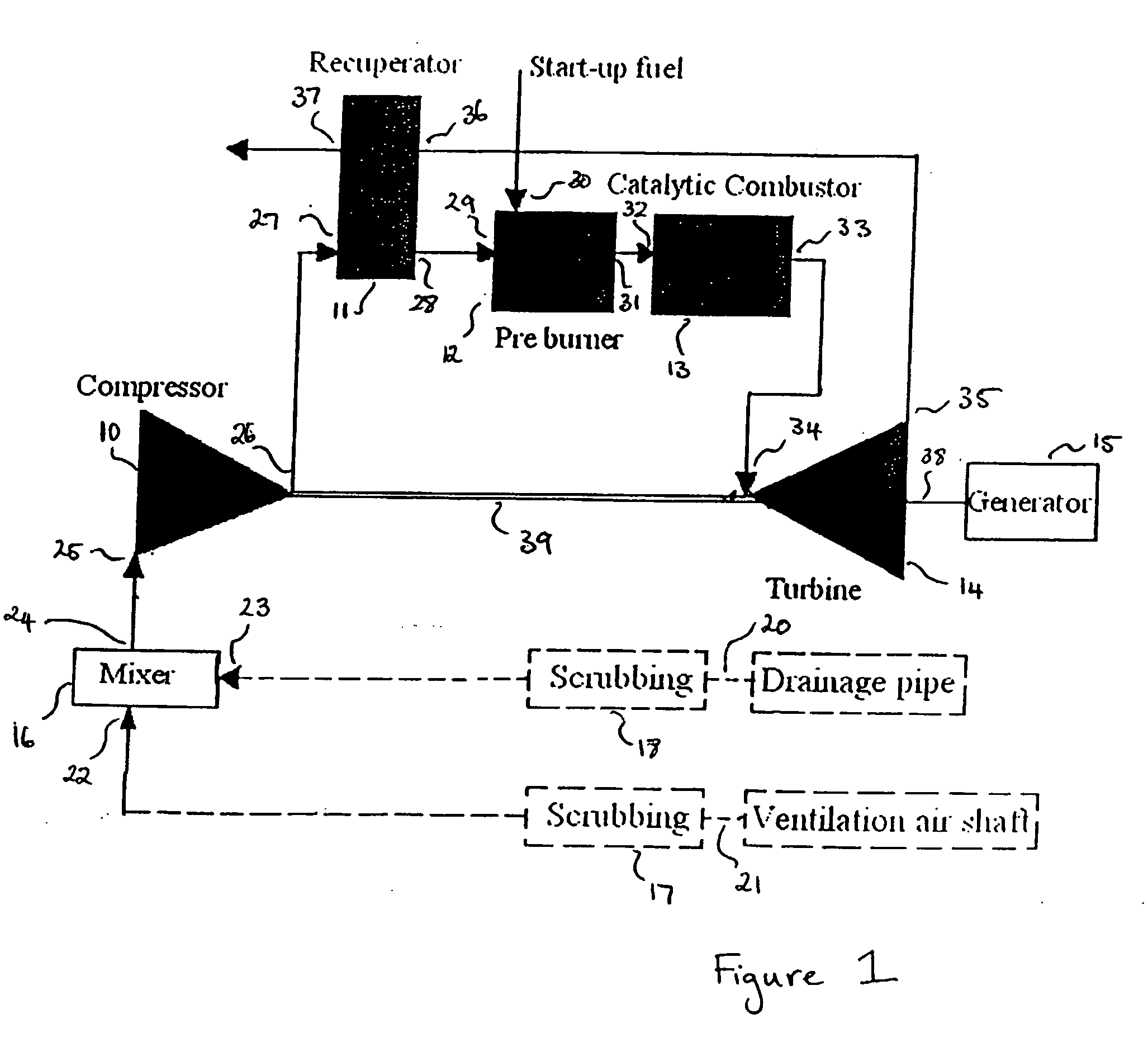
[0137] With reference to FIG. 1, a preferred embodiment of a catalytic combustion gas turbine system comprises a compressor 10, a recuperator 11, a pre-burner 12, a catalytic combustor 13, a turbine 14, a generator 15, a mixer 16, and first and second scrubbers 17, 18 thereby forming a power generation system which can be powered with approximately 1 mole % methane (maximum 1.5 mole %, minimum 0.5 mole %).

[0138] The system is predominantly powered by the methane in the ventilation air from a coal mine 21. The ventilation air is scrubbed in the first scrubber 17, to remove dust particles greater than and equal to 0.50 micron in diameter. The first scrubber 17 also removes hydrogen sulphide and sulphur dioxide so that the concentration of these compounds does not exceed the maximum allowable concentration in the system, which is 10 ppm for hydrogen sulphide and 5 ppm for sulphur dioxide. Exceedance of the maximum allowable concentrations can lead to fouling of the system components a...


PUM


Abstract

A system comprising a compressor (10) having an inlet stream (25) and an outlet stream (26), a pre-heater (12) having a process inlet stream (29) and a process outlet stream (31), a catalytic combustor (13) having an inlet stream (32) and an outlet stream (33) and containing an catalyst, and a turbine (14) having an inlet stream (34) and an outlet stream (35), wherein, the outlet stream (26) of the compressor(10) is connected to the process inlet stream (29) of the pre-heater (12), the process outlet stream (31) of the pre-heater (12) is connected to the inlet stream (32) of the catalytic combustor (13). The outlet stream (33) of the catalytic combustor (13) is connected to the inlet stream (34) of the turbine (14). During operation of the system, the inlet stream (25) of the compressor (10) has a substantially constant and low concentration of fuel.

Description

FIELD OF INVENTION [0001] This invention relates to catalytic combustion. BACKGROUND OF THE INVENTION [0002] A catalytic combustion gas turbine system has been developed to replace conventional industrial gas turbines, burning natural gas, but with ultra low NOx emissions. One of the features of this turbine is that cooling is required at the inlet of the turbine because of the high inlet temperature (>850° C.), arising from combustion of high concentrations of methane. This cooling is achieved by bypassing a substantial amount of the air from the compressor discharge to the turbine inlet and turbine first stage. However, if the air contains methane, this results in a large amount of uncombusted methane passing through the turbine and into the atmosphere. Not only is this an inefficient use of the methane, but it is also damaging to the environment and a waste of energy. [0003] Another application of catalytic combustion turbine systems has been to generate electricity from waste...

Claims


Application Information

Patent Timeline
IPC IPC(8): F23R3/40F02C3/22F02C7/08
CPCF02C3/04F02C3/22F02C7/08F02C7/224F23C13/02F23L15/04F23R3/40F05D2220/60F05D2220/76Y02E20/34
Inventor SU, SHIBEATH, ANDREW CHARLESMALLETT, CLIFFORD WILLIAM
Owner COMMONWEALTH SCI & IND RES ORG
Learn More