Surface treatment of concrete

Inactive Publication Date: 2006-07-13
NUCLEAR DECOMMISSIONING AUTHORITY +1
View PDF8 Cites 2 Cited by
  • Summary
  • Abstract
  • Description
  • Claims
  • Application Information

AI Technical Summary

Benefits of technology

[0013] The method of the invention, of laser scabbling using spots of laser light, significantly reduces the creation of areas treated by the laser light which subsequently resist further laser scabbling treatments, when compared to other known methods of applying laser light of substantially continuous power. In addition the method results in a flatter scabbled surface than with other known methods of laser scabbling.
[0024] In addition, laser scabbling processes may cause explosive detachment of surface fragments of a material being treated, as in the scabbling of concrete. To overcome potential shrapnel damage to the laser and associated optics, laser beams may be focussed through a relatively very small aperture before defocusing to form the spot. A high velocity stream of air may also be ejected under pressure from this aperture so as to prevent ingress of debris. Such focussing and defocusing may serve to increase the divergence of a laser beam, due to the surface to be treated being remote from the focus, and induce or increase a spread of power density within a spot of incident laser light.
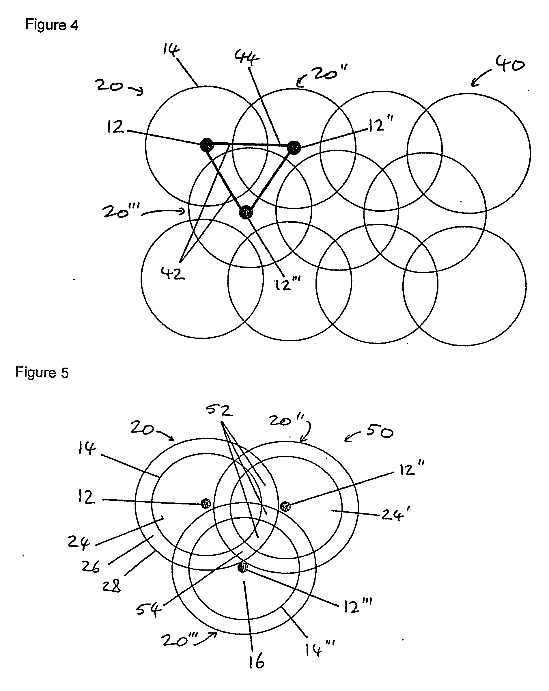
[0025] The use of spots, particularly overlapping spots, particularly sequential, of laser light to scabble a surface has been found to reduce the proportion of the treated surface which is treated by peripheral parts of a laser beam, i.e in which scabbling is inhibited because the power density of the laser does not reach the threshold for causing scabbling for the appropriate duration, and which may therefore inhibit further surface removal. Surprisingly, it has been found that whilst the area subjected to a lower incident laser beam power density, i.e. a power density below a critical threshold, is increased using the method of the invention as compared to a linearly scanned laser beam, the efficiency of surface removal is increased and a more even scabbled surface results.
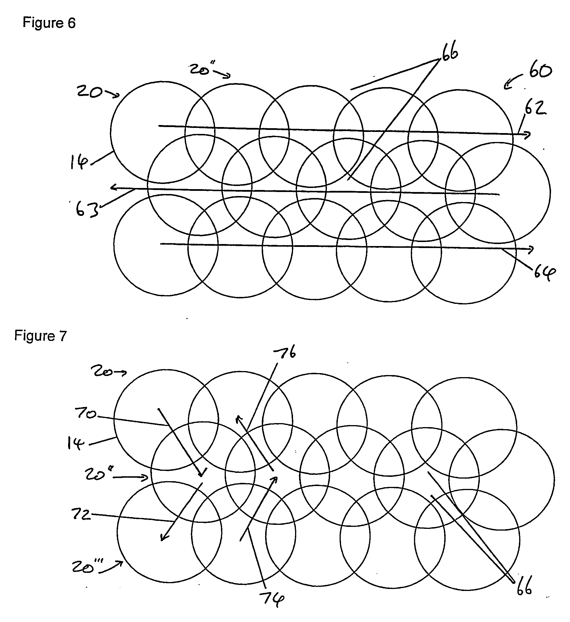
[0039] Any suitable method for moving the individual spots of laser light relative to the material being scabbled may be used including moving the laser, moving the object to be scabbled, moving a laser light conduit (such as a fibre-optic cable) or the employment of optical methods such as mirrors and the like. It is optionally within the scope of the invention to move a beam, without turning it off, at such a velocity that the beam has a negligible residence time between individual spots of laser light in proportion to the treatment time for each spot, such that individual successive incident spots of laser light are effectively created.
[0054] The method of the invention may typically be used for decontamination in conjunction with fume extraction, dust or solids collection and other subsidiary protective processes to prevent the spread of any contamination, particularly where radioactivity is involved.

Problems solved by technology

In the nuclear industry surfaces of concrete structures may become contaminated with radionuclides.
Typically this contamination is only present in a surface layer of concrete.
However, simple mechanical methods may be unsuitable for use where a potential for contamination makes it desirable for an operator to be remote from a surface to be operated upon.
In such a method energy from the laser light heats the surface and causes surface fragments to break away or be ejected, often violently, due to the generation of either steam or thermal stresses below the surface.
However, it has been found that some surfaces, including some types of concrete having aggregate therein, whilst able to be successfully laser scabbled on a first scan of the laser beam over the surface, may fail to scabble, or do so only with reduced efficiency, on areas which are either within or adjacent to a first scanned track when subjected to laser irradiation on either a subsequent re-treatment of the same area or on an adjacent scanned track.

Method used


Image

  • Surface treatment of concrete
  • Surface treatment of concrete
  • Surface treatment of concrete

Examples


Embodiment Construction

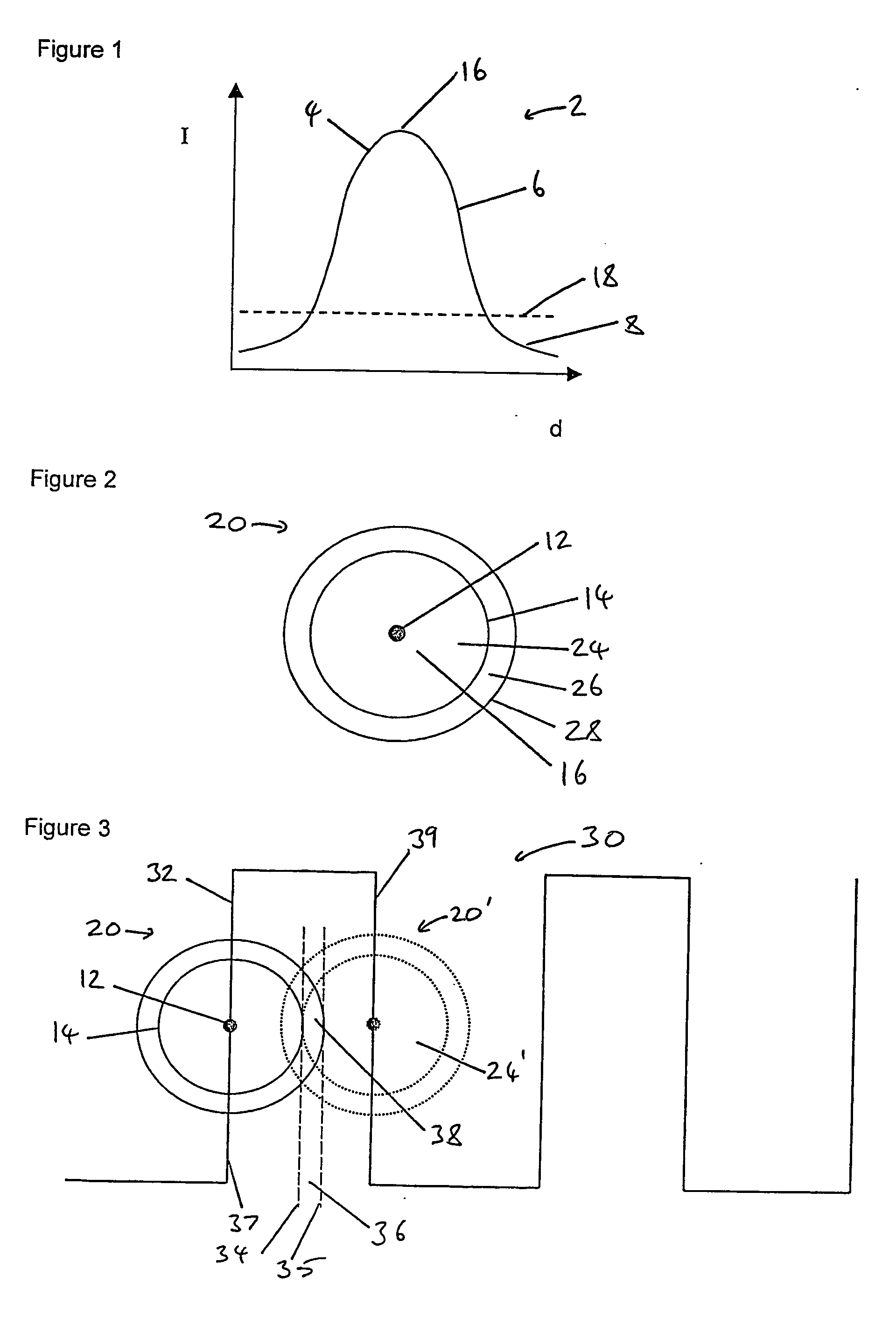
[0066] A beam of laser light may be non-uniform in power density across a width of the beam. A schematic representation of power density across a laser beam is shown in FIG. 1. FIG. 1 depicts a graph 2 with a y axis of laser power density (I) and an x axis of distance (d) across the beam. The curve 4 describes a quasi-Gaussian type power distribution from which it may be seen that the laser beam has a central area 16 of highest power density. The curve may be divided into two portions, the boundary between being defined by a threshold power density level 18. A portion 6 of the curve 4 above this power density threshold represents part of the laser beam capable of giving rise to scabbling of a surface, the portion 8 below represents an area not capable of giving rise to scabbling of such a surface. However, the low power density portion 8 may give rise to surface modification which makes the surface resistant to scabbling by subsequent passes with a laser beam, even if that subsequen...


PUM

PropertyMeasurementUnit
Timeaaaaaaaaaa
Timeaaaaaaaaaa
Timeaaaaaaaaaa

Abstract

A method of treating a surface for the removal of a surface portion comprising irradiating the surface with laser light, wherein the irradiation is effected by covering said surface in a sequential manner with a plurality of discrete spots of laser light. The spots of laser light overlap and may be arranged in a geometric arrangement defined by the locations of the centers of the spots of laser light. The spots of laser light may be applied sequentially.

Description

FIELD OF THE INVENTION [0001] The present invention concerns surface removal from inorganic non-metallic structures, in particular concrete structures, primarily though not exclusively for the purpose of removing radioactive contamination contained in surface layers. DISCUSSION OF THE PRIOR ART [0002] In the nuclear industry surfaces of concrete structures may become contaminated with radionuclides. Common contaminants include uranium oxide, plutonium oxide, strontium-90, caesium-137 and cobalt-60. Typically this contamination is only present in a surface layer of concrete. Such layers may be around 1 to 4 mm or more in thickness. By removal of such a surface layer the degree of contamination of a surface and of the structure as a whole may be greatly reduced. However, simple mechanical methods may be unsuitable for use where a potential for contamination makes it desirable for an operator to be remote from a surface to be operated upon. [0003] Various techniques are known for the s...

Claims


Application Information

Patent Timeline
IPC IPC(8): C23F1/00B08B7/00B23K26/40G21F9/00
CPCB08B7/0042B23K26/4075B28D1/00B28D1/221G21F9/005B23K26/40B23K2103/50
Inventor BROWN, STEPHEN CHRISTOPHER NEILSPENCER, JULIAN TIMOTHYBENJAMIN, ANDREW WILLIAMTHOMAS, TRISTAN GORONWY
Owner NUCLEAR DECOMMISSIONING AUTHORITY
Why Eureka
Try Eureka