Method and apparatus for conditioning liquid hydrocarbon fuels

a technology of liquid hydrocarbon fuel and conditioning method, which is applied in the direction of mechanical equipment, lighting and heating equipment, machines/engines, etc., can solve the problems of high emissions and achieve the effects of preventing heat loss, reducing emissions, and enhancing the vaporization process

Active Publication Date: 2006-07-13
LPP COMBUSTION LLC
View PDF111 Cites 17 Cited by
  • Summary
  • Abstract
  • Description
  • Claims
  • Application Information

AI Technical Summary

Benefits of technology

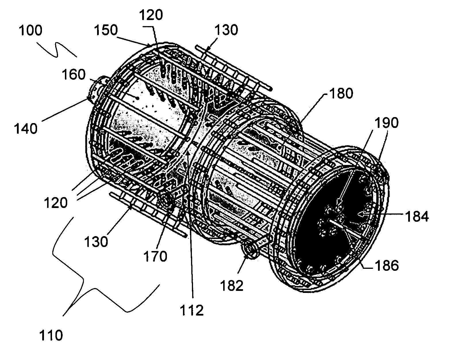
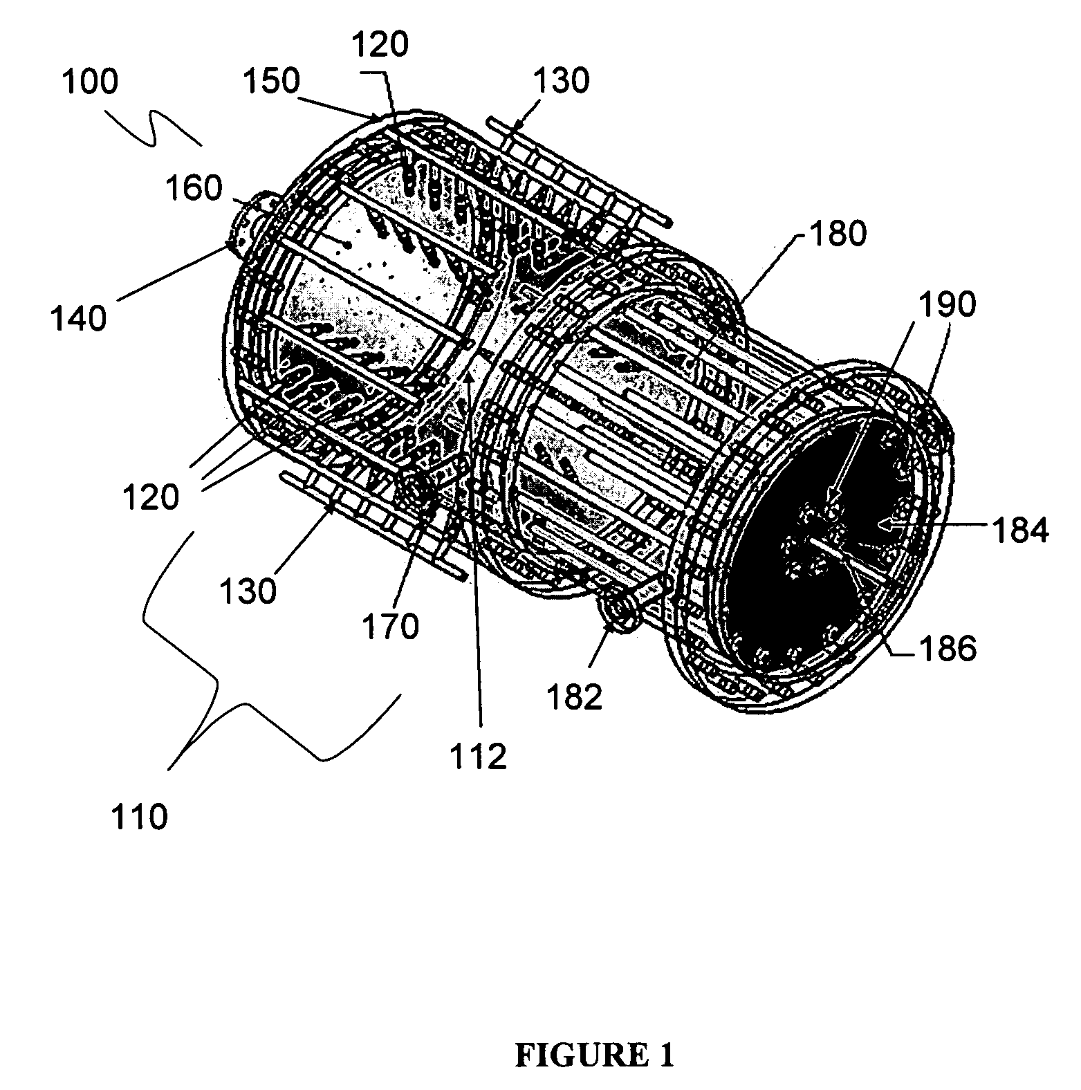
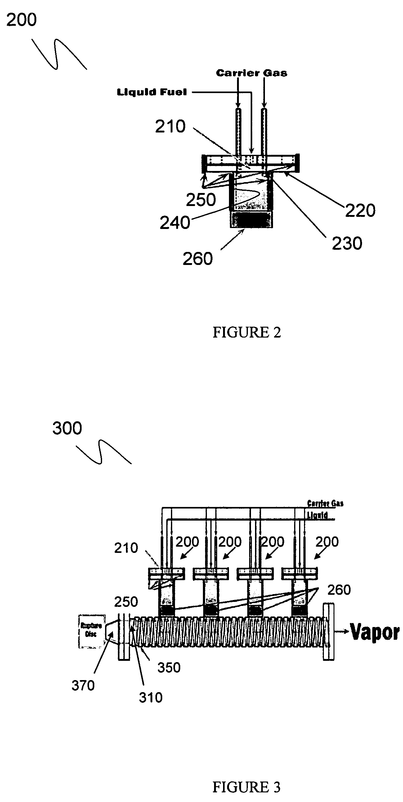
[0003] A method and apparatus for conditioning liquid fuels at a location external to a combustion device so that the resulting vapor phase fuel may be pre-mixed with air and burned under lean conditions, thus achieving low emissions, is described herein. Preferably, the liquid fuel is conditioned such that it may be used in a combustor configured for natural gas without modification to the combustor/fuel metering system. In one embodiment, the liquid fuel is sprayed into a vaporization chamber such that the spray does not impinge on any surface. The energy for vaporization i

Problems solved by technology

This results in a diffusion flame in which the fuel is burned in a

Method used


Image

  • Method and apparatus for conditioning liquid hydrocarbon fuels
  • Method and apparatus for conditioning liquid hydrocarbon fuels
  • Method and apparatus for conditioning liquid hydrocarbon fuels

Examples


Embodiment Construction

[0009] Various embodiments of methods and apparatuses for conditioning liquid fuels are discussed below. Specific details are set forth in order to provide a thorough understanding of the present invention. The specific embodiments described below should not be understood to limit the invention. Additionally, for ease of understanding, certain method steps are delineated as separate steps. These steps should not be understood as necessarily distinct or order-dependent in their performance unless so indicated.

[0010] The complete disclosure of U.S. patent application Ser. No. 10 / 682,408, which was filed Oct. 10, 2003, and which describes methods and devices for vaporizing, mixing, and delivering liquid fuels or liquefied gases which have been pre-vaporized with a reduced oxygen content air stream for use in combustion devices, is fully incorporated herein by reference. In addition, U.S. Patent Application Ser. No. 60 / 535,716, filed Jan. 12, 2004, and Ser. No. 11 / 033,180, filed Jan. 1...


PUM


Abstract

In one embodiment of a method for vaporizing liquids such as fuels, the liquid is sprayed into a chamber such that the spray does not impinge on any surface. The energy for vaporization is supplied through the injection of a hot diluent such as nitrogen or oxygen depleted air. Additional heat is added through the surface. In another embodiment, the liquid is sprayed onto a hot surface using a geometry such that the entire spray is intercepted by the surface. Heat is added through the surface to maintain an internal surface temperature above the boiling point of the least volatile component of the liquid. The liquid droplets impinging on the surface are thus flash vaporized. A carrier gas may also be flowed through the vaporizer to control the dew point of the resultant vapor phase mixture.

Description

[0001] This application claims priority from U.S. provisional patent application Ser. No. 60 / 634,221 filed Dec. 8, 2004, the content of which is incorporated fully herein by reference.BACKGROUND INFORMATION [0002] Low emissions from combustion devices are obtained by burning a lean mixture of fuel and air obtained by pre-mixing gaseous fuel and air. Dry Low NOx (DLN) technology gas turbines, for example, typically burn natural gas under lean, pre-mixed conditions. Liquid fuels, by contrast, are typically burned by injecting a fuel spray directly into the combustor. This results in a diffusion flame in which the fuel is burned in a locally stoichiometric fuel / air mixture and causes high emissions. Under certain conditions, burning a liquid fuel is more desirable than burning a gaseous fuel. However, it would be desirable to avoid the high emissions associated with diffusion flames when burning such liquid fuels. SUMMARY [0003] A method and apparatus for conditioning liquid fuels at a...

Claims


Application Information

Patent Timeline
IPC IPC(8): F23C7/00F23M3/00
CPCF23K5/22F23K2301/205F23D11/441F23K2300/205F02C1/00F02B43/08F02G3/00F23N5/00
Inventor RAMOTOWSKI, MICHAEL J.JOKLIK, RICHARDFULLER, CASEYGOKULAKRISHNAN, PONNUTHURAIESKIN, LEOGAINES, GLENNROBY, RICHARD J.KLASSEN, MICHAEL S.
Owner LPP COMBUSTION LLC
Why Eureka
Try Eureka