
Filter apparatus, exposure apparatus, and device-producing method

Active Publication Date: 2006-07-20
NIKON CORP
View PDF11 Cites 32 Cited by
  • Summary
  • Abstract
  • Description
  • Claims
  • Application Information

AI Technical Summary

Benefits of technology

[0015] The present invention focuses on the problems of the prior art. It is an object of the present invention to provide a filter apparatus that improves temperature stability of a gas while maintaining a high impurity removing capacity. Further, it is an object of the present invention to provide an exposure apparatus that obtains a higher and more stable exposure precision. Moreover, it is an object of the present invention to provide a method for manufacturing a high integration device with efficiency.

Problems solved by technology

The exposure apparatus is a very delicate apparatus and the temperature in the apparatus must be kept constant for each part of the exposure apparatus to function properly.
However, the following problems arise when using exposure light having a short wavelength.
However, in many cases, the humidity of the clean room is not sufficiently adjusted in terms of the control range or control cycle etc.
Further, an enormous equipment investment would become necessary to perform humidity management in a large clean room with satisfactory accuracy.

Method used


Image

  • Filter apparatus, exposure apparatus, and device-producing method
  • Filter apparatus, exposure apparatus, and device-producing method
  • Filter apparatus, exposure apparatus, and device-producing method

Examples


first embodiment

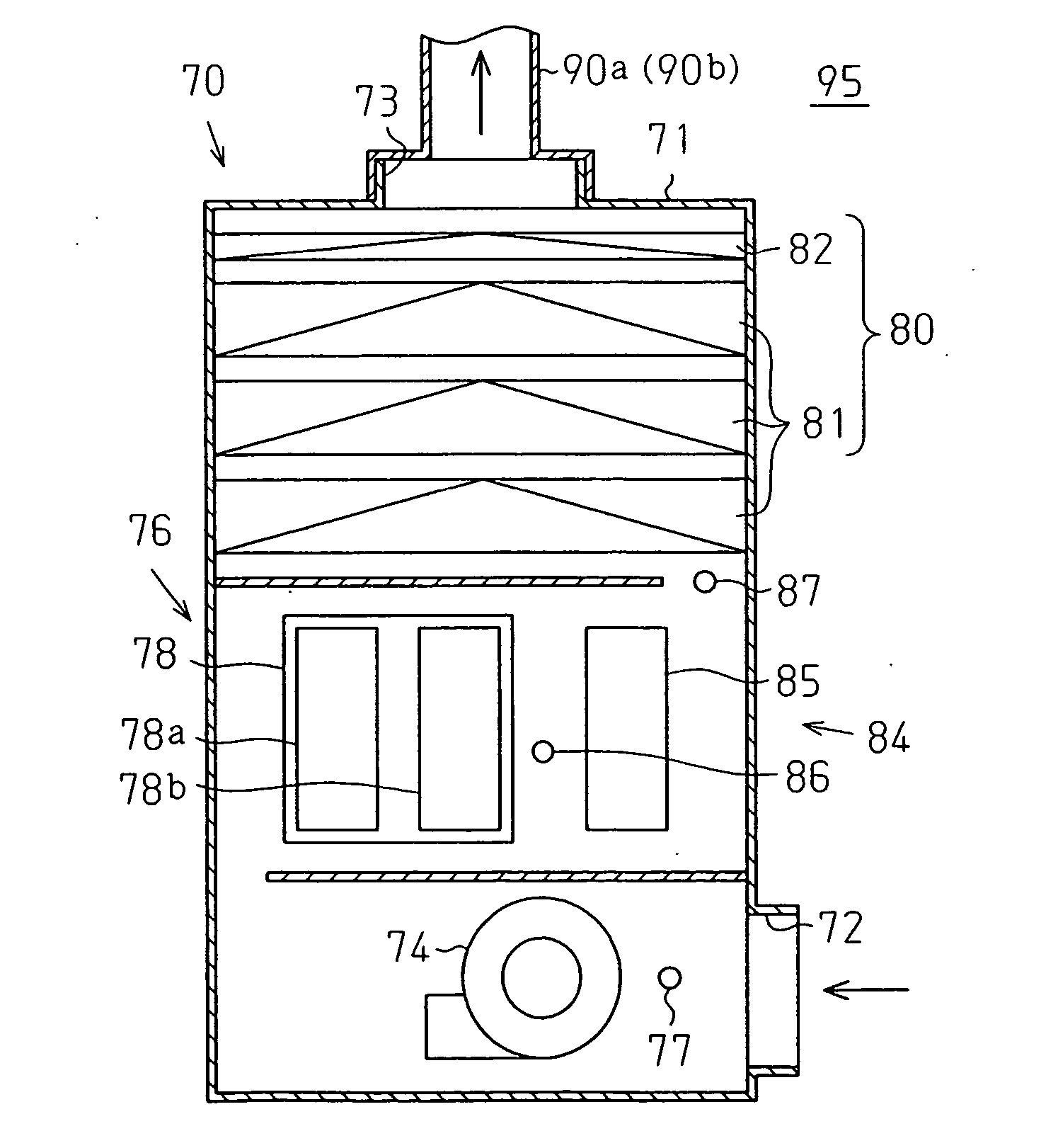
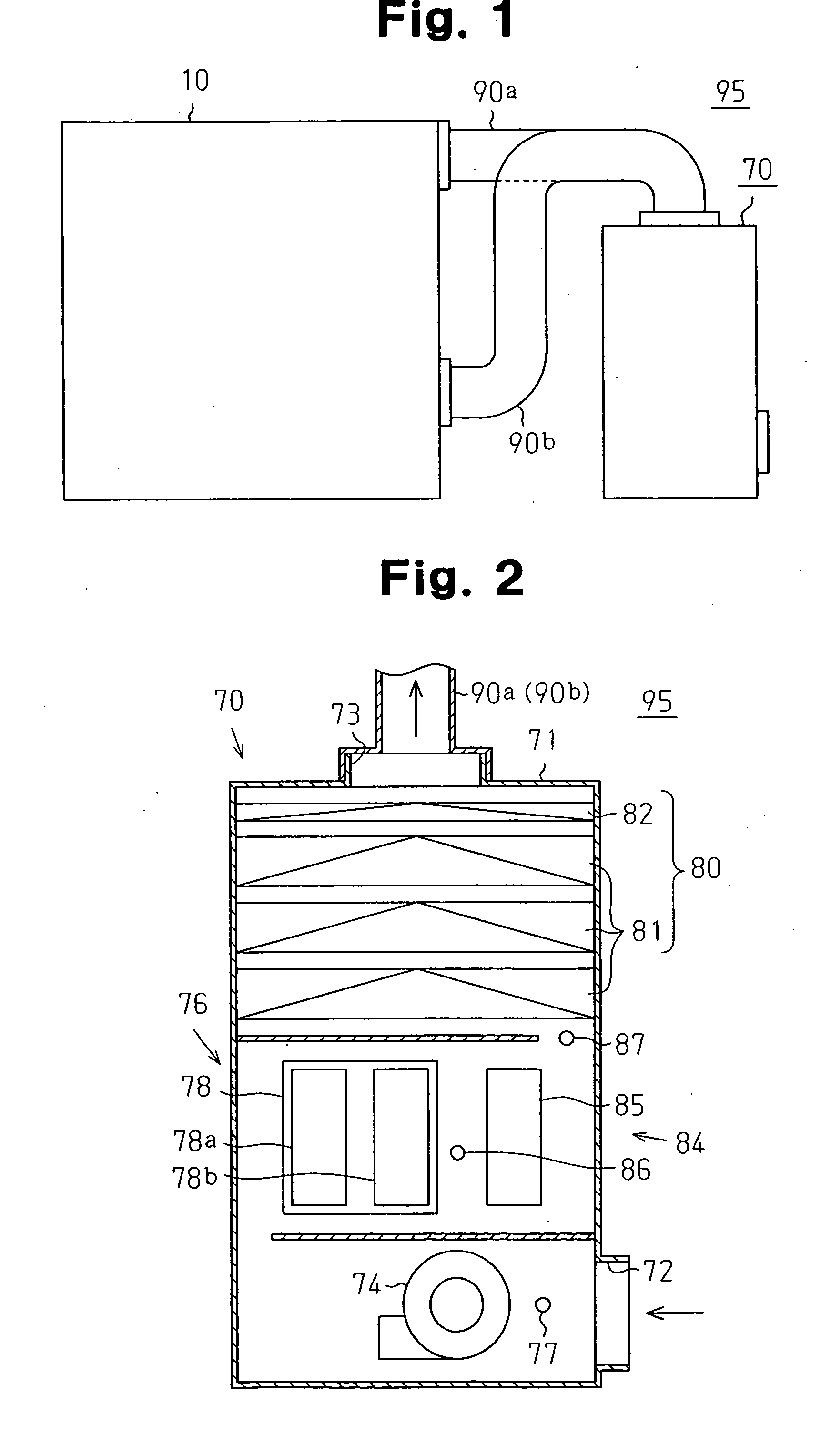
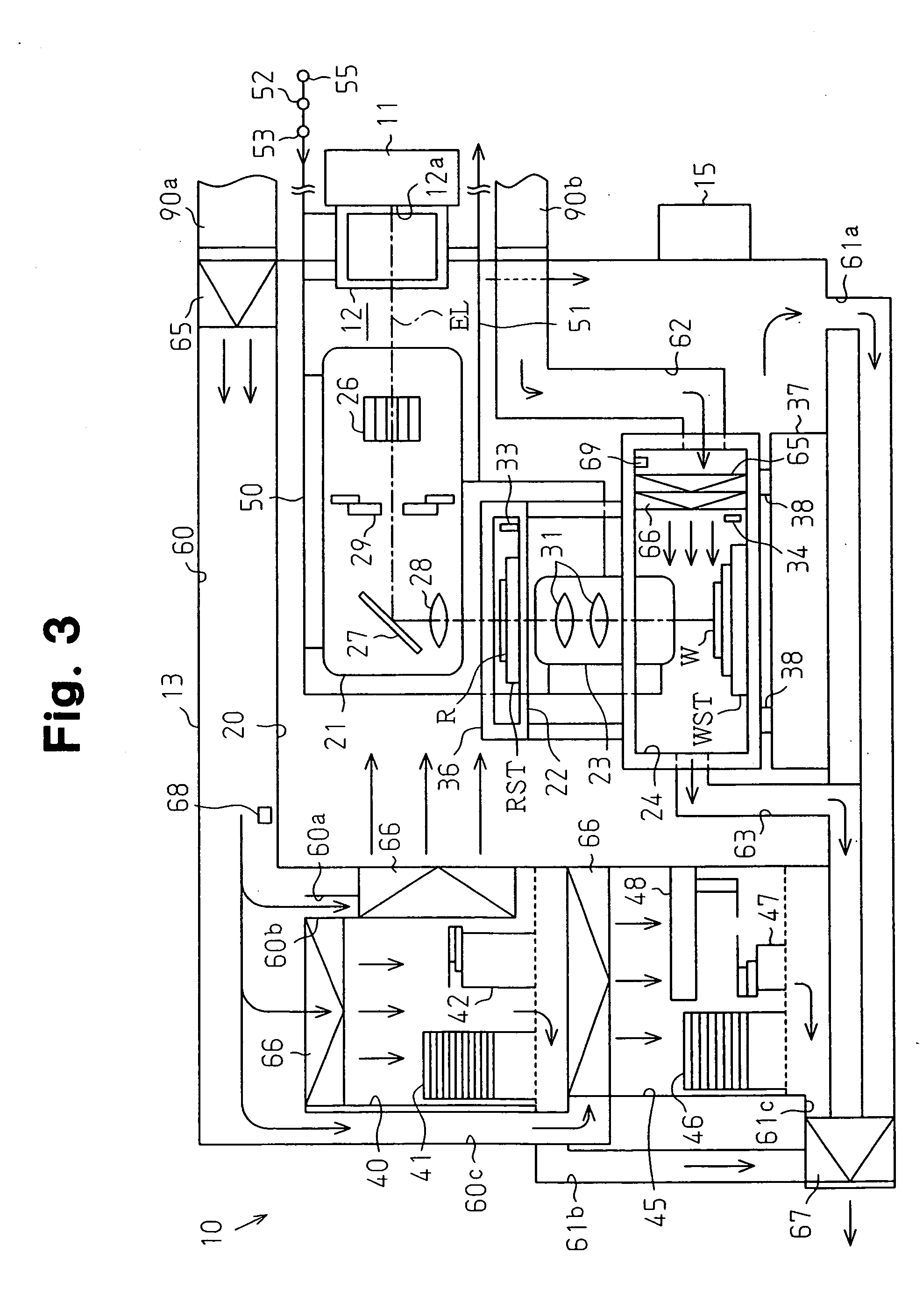
[0028] A filter apparatus for removing impurities from air, an exposure apparatus for manufacturing semiconductor devices, and a method for manufacturing semiconductor devices according to a first embodiment of the present invention will now be described with reference to FIGS. 1 to 3.

[0029] As shown in FIG. 1, an exposure apparatus 10 is connected to a filter apparatus 70 by ducts 90a and 90b. The ducts 90a and 90b are formed from material that produces only a small production amount of contaminants, such as stainless steel (SUS) or fluorocarbon resin. Such contaminants collect on the surface of various types of optical elements and lower the optical capacity of the optical elements. The exposure apparatus 10 and the filter apparatus 70 are arranged in a clean room 95 that can be adjusted to a predetermined temperature.

[0030] As shown in FIG. 3, the exposure apparatus 10 includes an exposure light source 11, a beam matching unit (hereinafter referred to as “BMU”) 12, and a main b...

second embodiment

[0103] A structure for drawing air into the main body chamber 13 from the clean room 95 through the filter apparatus 70 and the ducts 90a and 90b is described for the exposure apparatus 10 of the first embodiment. In the second embodiment, an example for applying the filter apparatus 70 of the present invention to the exposure apparatus 10 including the main body chamber 13 and a machine compartment 100 arranged adjacent to the main body chamber 13 will be discussed with reference to FIG. 4.

[0104] A machine compartment air inlet port 102 for drawing in the air from the filter apparatus 70 is formed in a lower part of the side of a machine compartment main body 101 of the machine compartment 100, as shown in FIG. 4. The machine compartment air inlet port 102 is connected to the discharge port 73 of the filter apparatus 70 by a duct 90c.

[0105] A cooler (dry coil) 103 is arranged in the machine compartment main body 101 at a position slightly lower from the center in the height direc...


PUM

PropertyMeasurementUnit
Temperatureaaaaaaaaaa
Photosensitivityaaaaaaaaaa
Humidityaaaaaaaaaa

Abstract

A filter apparatus for improving gas temperature stability while maintaining a high impurity removal capacity. The filter apparatus includes a filter for removing impurities from a gas and a temperature adjuster for adjusting the temperature of the gas to a predetermined temperature. The filter apparatus further includes a humidity detector, arranged at the upstream side of the filter, for adjusting the humidity of the gas before the gas passes through the filter.

Description

CROSS-REFERENCE TO RELATED APPLICATIONS [0001] This application is a continuation application based upon International Patent Application No. PCT / JP2004 / 007629, filed on Jun. 2, 2004, the entire contents of which are incorporated herein by reference.BACKGROUND OF THE INVENTION [0002] The present invention relates to a filter apparatus for removing impurities from a gas and for adjusting the humidity of a gas. The present invention further relates to an exposure apparatus used in the photolithography step of a manufacturing process for various devices such as a semiconductor element, a liquid crystal display element, an imaging element, a thin-film magnetic head and the like. The present invention further relates to a device manufacturing method for manufacturing various devices. [0003] In this type of exposure apparatus, an illumination optical system illuminates a mask, such as a reticle or a photomask, having a predetermined pattern with predetermined exposure light. Further, the ...

Claims


Application Information

Patent Timeline
IPC IPC(8): B01D46/00B01D46/42G03F7/20
CPCB01D46/0001B01D46/0036B01D46/4263B01D2279/51G03F7/70858G03F7/70933Y10S55/34
Inventor UDAGAWA, KENJINAGAHASHI, YOSHITOMO
Owner NIKON CORP
Learn More