
Cleaning method for semiconductor wafer

a cleaning method and technology for semiconductors, applied in the direction of cleaning processes and apparatus, cleaning using liquids, cleaning processes and processes, etc., can solve the problems of affecting the cleaning effect of semiconductor wafers, so as to prevent severe loss of silicon nitride, improve the problem of slurry residues, and improve the effect of slurry residues

Inactive Publication Date: 2006-07-20
UNITED MICROELECTRONICS CORP
View PDF7 Cites 6 Cited by
  • Summary
  • Abstract
  • Description
  • Claims
  • Application Information

AI Technical Summary

Benefits of technology

[0015] It is an advantage of the claimed invention that it provides at least two steps of a cleaning process that can solve problems faced in the prior art. The brushing step improves the slurry residues issue in the prior art, so as to prevent defects on the surface of the wafer. Another step, in which the brush is not contact with the wafer, can prevent severe loss of the silicon nitride that results from long duration of brushing. In other words, decreasing brushing time appropriately may assure the uniformity of the silicon nitride, and thus maintains the reliability of the wafer.

Problems solved by technology

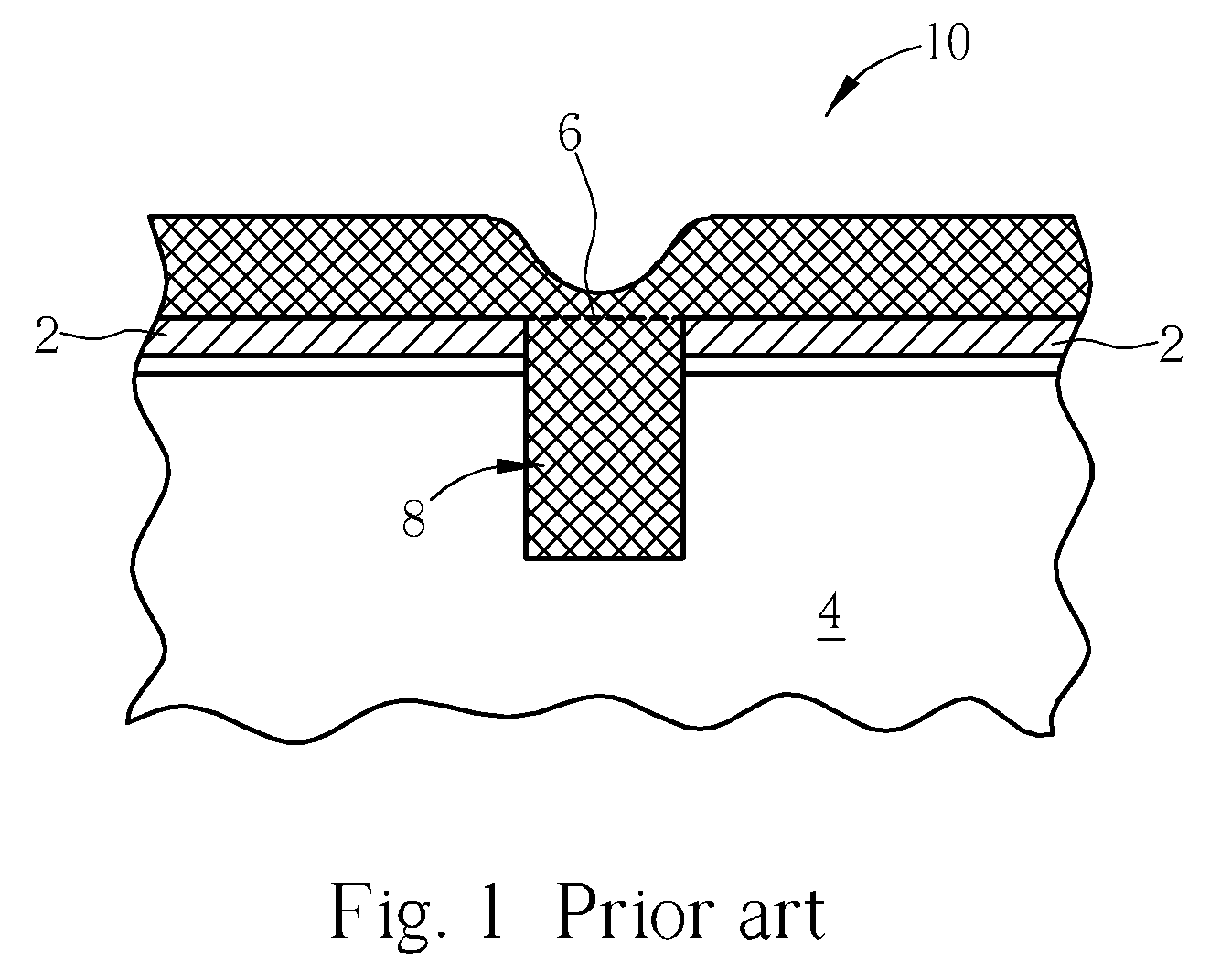
However, these elements form severe topographies on the semiconductor wafer, and thus make deposition or pattern transfer processes difficult.
However, in processes with feature sizes smaller than 250 nm, global planarization can not be performed by using SOG or REB.
If the openings 8 are clogged, the trenches will not be able to be filled with the silicon oxide, which leads to defects in elements.
However, although using HSS in a STI CMP process may enhance the polishing performance, it may cause microscratches on the wafer, and leaving residues.
The slurry residues and shattered pieces resulting from polishing may cause collapse of oxides, electric leakages or other defects.
However, in a STI CMP process adopting HSS, the above post clean process is not able to remove the residues thoroughly.
This is because that HSS comprises special surfactants, which are used to control the removing rate of silicon nitride and silicon oxide, and those surfactants may cause more severe residues problems.
Such a cleaning process is able to remove the residues effectively, and the oxide loss of the surface is rare.
However, such kind of cleaning process may lead to non-uniformity of the silicon nitride.

Method used


Image

  • Cleaning method for semiconductor wafer
  • Cleaning method for semiconductor wafer
  • Cleaning method for semiconductor wafer

Examples


Embodiment Construction

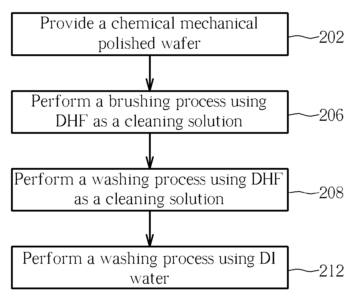
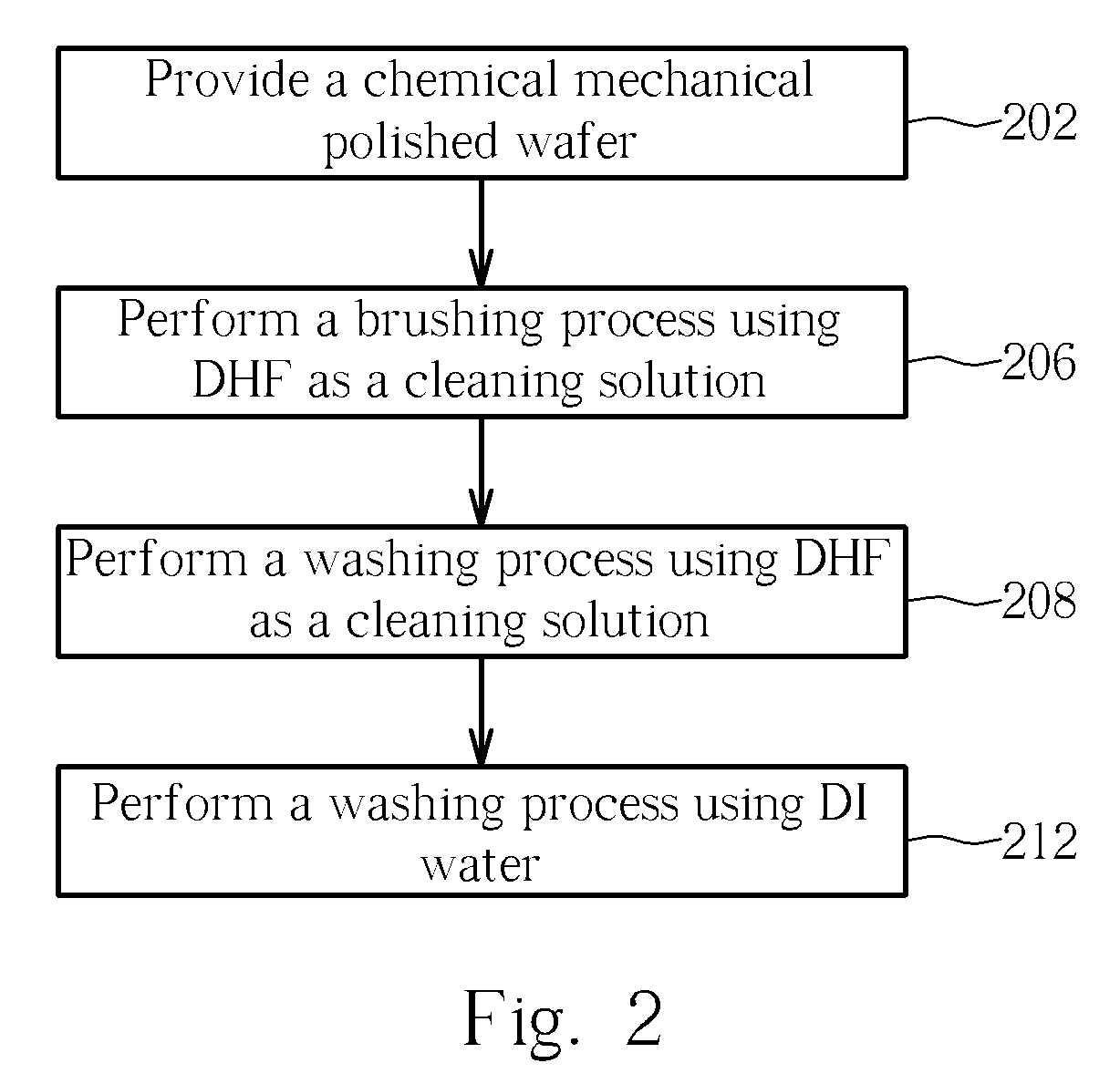
[0022] Please refer to FIG. 2. FIG. 2 illustrates a flow chart of one embodiment according to the present invention. As shown in FIG. 2, a dilute hydrogen fluoride (DHF) solution is provided on the chemical mechanical polished wafer, while the wafer is brushed for 45 seconds (step 206). Following that, the DHF solution is continually provided on the wafer for 15 seconds without brushing the wafer (step 208). At last, a washing process using DI water may be performed to wash away the cleaning solution and other remainders (step 212).

[0023] Please refer to FIG. 3. FIG. 3 illustrates a flow chart of another embodiment according to the present invention. As shown in FIG. 3, an ammonia (NH4OH) solution is provided on the chemical mechanical polished wafer to perform a pre-brushing process or a pre-washing process (step 304). After that, DI water is provided to wash out the ammonia solution (step 305). A DHF solution is then provided on the wafer, while the wafer is brushed for 45 second...


PUM

PropertyMeasurementUnit
feature sizesaaaaaaaaaa
feature sizeaaaaaaaaaa
processing timeaaaaaaaaaa

Abstract

A cleaning method according to the present invention is provided. The method includes at least two stages of cleaning processes. In the first stage, dilute HF is provided as a cleaning solution, and a brushing process is performed. In the second stage, dilute HF is also provided as a cleaning solution, and a washing process is performed. A pre-cleaning process and a post-cleaning process are further provided according to the present invention. The pre-cleaning method is performed before the brushing process, and the post-cleaning method is performed after the washing process. In addition, the pre-cleaning process and the post-cleaning process are a brushing process or a washing process adopting NH4OH as a cleaning solution.

Description

BACKGROUND OF INVENTION [0001] 1. Field of the Invention [0002] The present invention is related to a cleaning method for cleaning a semiconductor wafer. More particularly, the present invention is related to a cleaning method for cleaning a chemical mechanical polished semiconductor wafer. [0003] 2. Description of the Prior Art [0004] As elements of a wafer become smaller and more integrated, the requirement of controlling the depth of focus of the lithography grows as well. As a result, in VLSI and ULSI, a plurality of layers of metal interconnects and low K dielectric materials are widely adopted to connect elements of a semiconductor wafer, so as to form high-density circuits. However, these elements form severe topographies on the semiconductor wafer, and thus make deposition or pattern transfer processes difficult. Therefore, a planarization process has to be performed on the wafer surface before further processing. [0005] Conventional planarization is mostly performed using s...

Claims


Application Information

Patent Timeline
Patent Type & Authority Applications(United States)
IPC IPC(8): C23G1/02B08B7/00C23G1/00
CPCH01L21/02052H01L21/02065
Inventor TSAI, TENG-CHUNCHU, HSIN-KUNHUANG, CHIEN-CHUNG
Owner UNITED MICROELECTRONICS CORP
Learn More