Membrane cartridge, membrane separating device, and membrane separating method

Inactive Publication Date: 2006-07-20
ASAHI KASEI CHEM CORP
View PDF2 Cites 2 Cited by
  • Summary
  • Abstract
  • Description
  • Claims
  • Application Information

AI Technical Summary

Benefits of technology

[0006] The present invention relates to a membrane cartridge, a membrane separating method, and a membrane separating device, which use a minimum required amount of aeration to prevent sludge aggregates and contaminants from accumulating on a hollow fiber membrane cartridge and to maintain a membrane filtration performance over a long period.
[0007] The inventors have devoted themselves to examinations to find that the use of the structure described below for a hollow fiber membrane cartridge minimizes bubbles of aerated air from the bottom of the lower ring dissipating out of the cartridge. Further, they have found that the structure described below allows at least a specified dimension of gaps to be present between hollow fiber membrane bundles near the cartridge head. This allows sludge aggregates and contaminants to slip out from the cartridge without accumulating between the hollow fiber membranes bundles. The inventors have thus completed the present invention.
[0017] By operating a hollow fiber membrane cartridge and a membrane separation device in accordance with the present invention, it is possible to prevent sludge from accumulating on the surfaces of the hollow fiber membranes and to inexpensively achieve a stable filtration performance over a long period.

Problems solved by technology

If hollow fiber membranes are used for the membrane cartridge, the high strength of the membranes themselves reduces the chances of the surfaces of the membranes from being damaged as a result of contact with contaminants contained in the raw water.
As a result, filtration efficiency will be lowered, thus preventing a stable filtration from being maintained over a long period.
However, in this case, the rising bubbles exert a force on the aggregates of activated sludge and the contaminants that drive them upward.
A further increase in the amount of aeration increases the number of sludge aggregates and contaminants passing between the hollow fiber membranes.
As a result, more aggregates and contaminants accumulate in the bundle near the cartridge head.
This may cause the surfaces of the hollow fiber membranes to be blocked.

Method used


Image

  • Membrane cartridge, membrane separating device, and membrane separating method
  • Membrane cartridge, membrane separating device, and membrane separating method
  • Membrane cartridge, membrane separating device, and membrane separating method

Examples


example 1

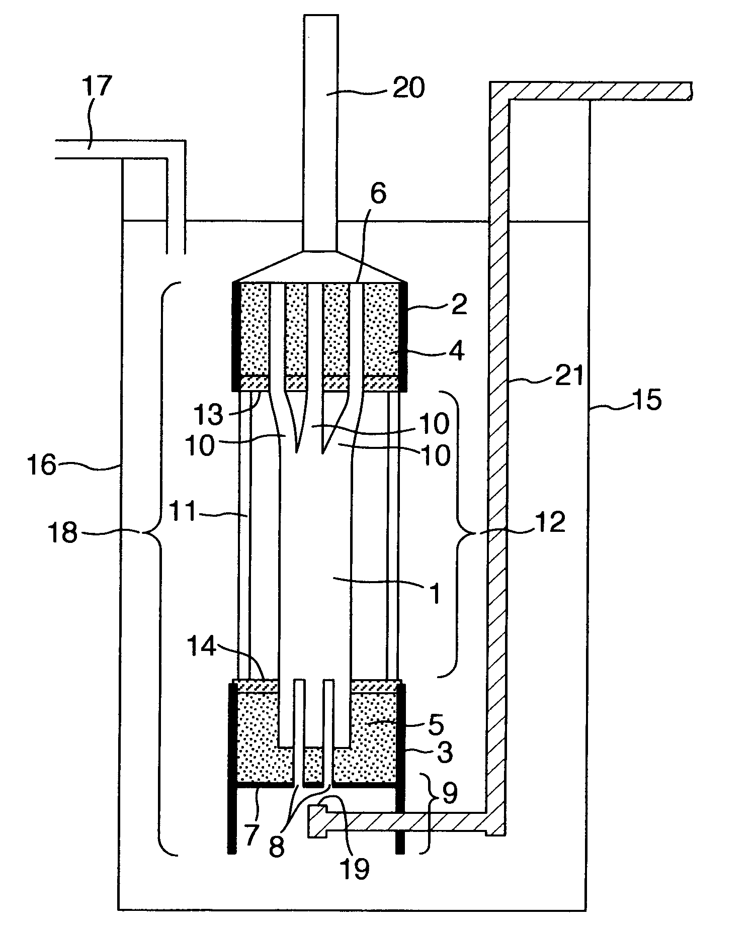
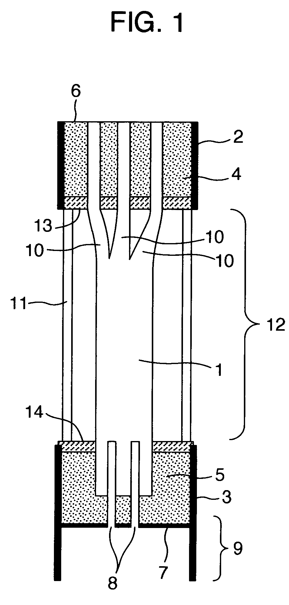
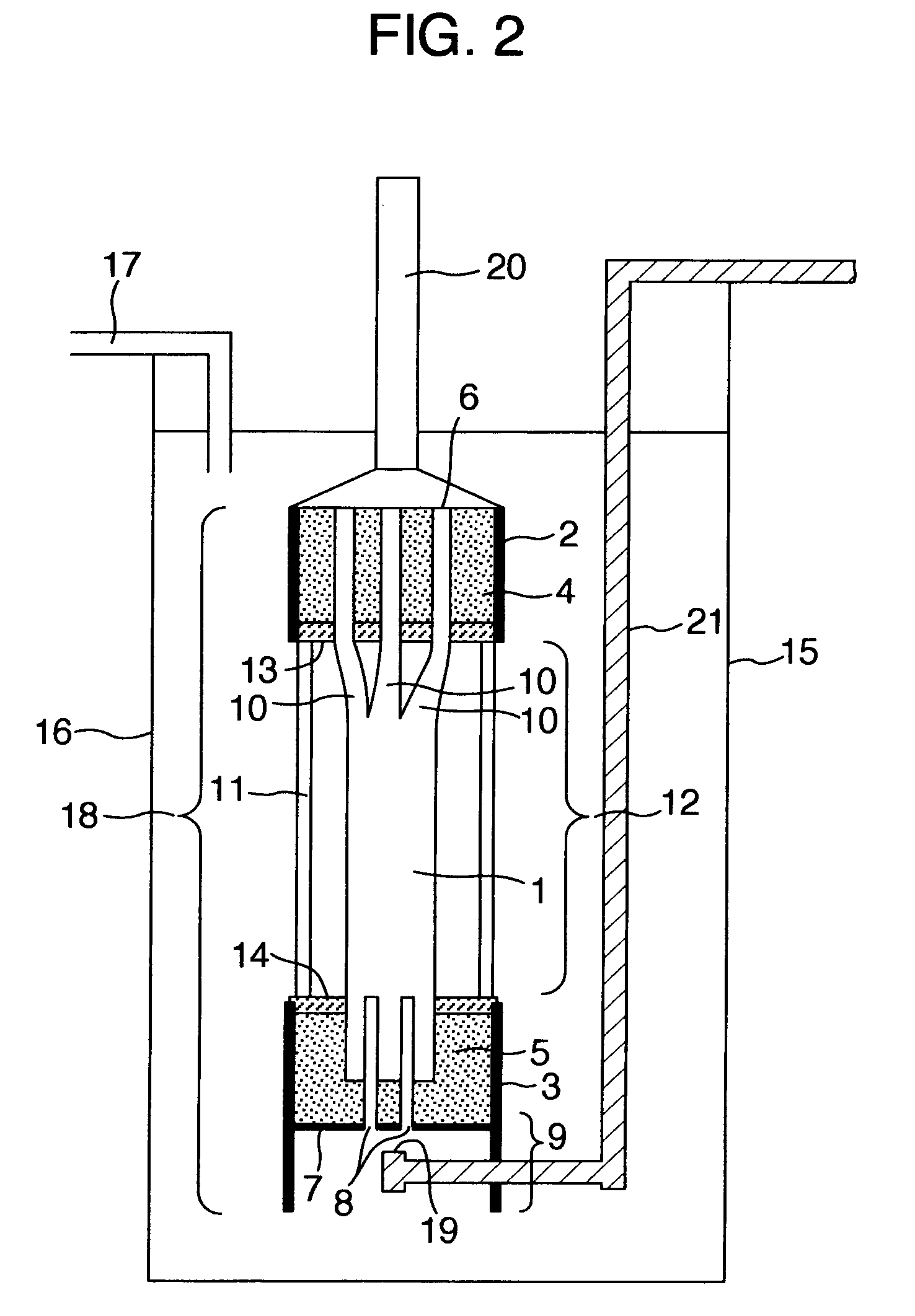
[0069] A cylindrical hollow fiber membrane cartridge described below was produced. The opposite ends of each of the plurality of hollow fiber membranes were fixedly bonded to the cartridge. The cartridge had a cartridge head fixedly bonded to the outer periphery of one end in a liquid tight manner and a lower ring fixedly bonded to the outer periphery of the other end in a liquid tight manner. The cartridge had a membrane area of 25 m2. The hollow fiber membranes were precision filtration membranes made of polyvinylidene fluoride and had a pore size of 0.1 μm. Each of the hollow fiber membranes had an outer diameter of 1.4 mm and an inner diameter of 0.8 mm. The effective length of the membrane between the filtration section interfaces of the cartridge head-side and lower ring-side adhesion fixation layers was 2,000 mm. The adhesion fixation layers at the opposite ends of the hollow fiber membranes had a diameter of about 150 mm.

[0070] At the filtration section interface of the car...

example 2

[0076] At the filtration section interface of the cartridge head-side adhesion fixation layer, 110 hollow fiber membranes were bundled per small bundle. The number of small bundles was 30, and the spacing between the small bundles was 1.5 mm. A membrane separation device was produced in the same manner as in Example 1 except it had an arrangement as shown in FIG. 4(b).

[0077] The membrane separation device was immersed in an activated sludge tank and operated as in the case with Example 1. Then, the inter-membrane differential pressure remained stable at −15 to −20 kPa for three months. After the three months of operation, sludge fouling or contaminants adhering to the cartridge weighed 2.53 kg, indicating a small amount of the fouling.

example 3

[0078] At the filtration section interface of the cartridge head-side adhesion fixation layer, 110 hollow fiber membranes were bundled per small bundle. The number of small bundles was 30, and the spacing between the small bundles was 2.0 mm. A membrane separation device was produced in the same manner as in Example 1 except it had an arrangement as shown in FIG. 4(c).

[0079] The membrane separation device was immersed in an activated sludge tank and operated as in the case with Example 1. Then, the inter-membrane differential pressure remained stable at −15 to −20 kPa for three months. After the three months of operation, sludge fouling or contaminants adhering to the cartridge weighed 2.03 kg, indicating a small amount of the fouling.


PUM

PropertyMeasurementUnit
Distanceaaaaaaaaaa
Distanceaaaaaaaaaa
Adhesion strengthaaaaaaaaaa

Abstract

A membrane separating method and a membrane separating device capable of preventing sludge from being accumulated on the surface of hollow fiber membranes in a membrane cartridge and having filtration performance stably sustained for a long period. The membrane cartridge formed by sticking and fixing both ends of two or more hollow fiber membranes arranged in the vertical direction is formed in such a structure that the collected state of the hollow fiber membranes on an upper side adhesive boundary surface is divided into a plurality of hollow fiber membrane bundles.

Description

TECHNICAL FIELD [0001] The present invention relates to a pressure or suction type tank filter device, and to a filter cartridge using hollow fiber membranes to be installed in an immersion type filter device. More specifically, the present invention relates to a hollow fiber membrane cartridge used for a filter device that removes turbidity and bacteria from raw water such as river water, lake water, underground water, seawater, domestic waste water, industrial waste water, or sewage secondary treated water, or for a membrane separation activated sludge device that uses membranes to separate activated sludge into solids and liquids. BACKGROUND ART [0002] As a waste water treatment method, there has been used a membrane separation activated sludge method in which a membrane cartridge is immersed in an activated sludge tank and a solid-liquid separation is carried out between the activated sludge and the treated water after treatment. This method allows the concentration of the activ...

Claims


Application Information

Patent Timeline
IPC IPC(8): B01D63/06B01D63/02B01D63/04B01D65/08C02F1/44
CPCB01D63/022B01D63/024B01D63/04B01D65/08B01D2315/06B01D2321/04B01D2321/185C02F3/1273Y02W10/10C02F1/44B01D69/08B01D2313/44B01D2313/042B01D63/0233
Inventor HASHIMOTO, TOMOTAKAOKAMURA, DAISUKE
Owner ASAHI KASEI CHEM CORP
Why Eureka
Try Eureka