Capillary array and related methods

a capillary array and array technology, applied in the field of diagnostics, can solve the problems of inefficient manner, limited range, and ineffective array methods, and achieve the effect of increasing the speed at which assays can be run, and improving the efficiency of target analyte-binding partner binding

Inactive Publication Date: 2006-07-20
RGT UNIV OF CALIFORNIA
View PDF23 Cites 32 Cited by
  • Summary
  • Abstract
  • Description
  • Claims
  • Application Information

AI Technical Summary

Benefits of technology

[0013] To enhance target analyte mixing and presentation to the binding partners affixed in the channel, the sample can be divided into at least two segments that are separated by a bolus or bubble of a fluid that is immiscible with the sample.
[0015] The use of boluses or bubbles of immiscible fluid in the methods of the invention improves the efficiency of target analyte-binding partner binding and therefore increases the speed at which assays can be run. In preferred embodiments, the sample is transported through the channel at a velocity of at least about 1 mm / second. Any fluid transport method can be employed, but fluid is preferably transported by electrophoretic force.

Problems solved by technology

The conventional array approaches described above, while powerful, are limited by the inefficient manner in which probe is used and by the long hybridization times required.
These limitations arise from the need to distribute probe molecules over a large surface during hybridization.
As a result, most probe molecules are far from the targets to which they might hybridize and sensitivity suffers.
This reduces the rate at which hybridization occurs and results in most probe molecules never reaching the targets to which they might bind, a phenomenon that becomes increasingly limiting for long oligonucleotides with slow diffusion rates.

Method used


Image

  • Capillary array and related methods
  • Capillary array and related methods

Examples


example 1

Capillary-Based Array Hybridization System

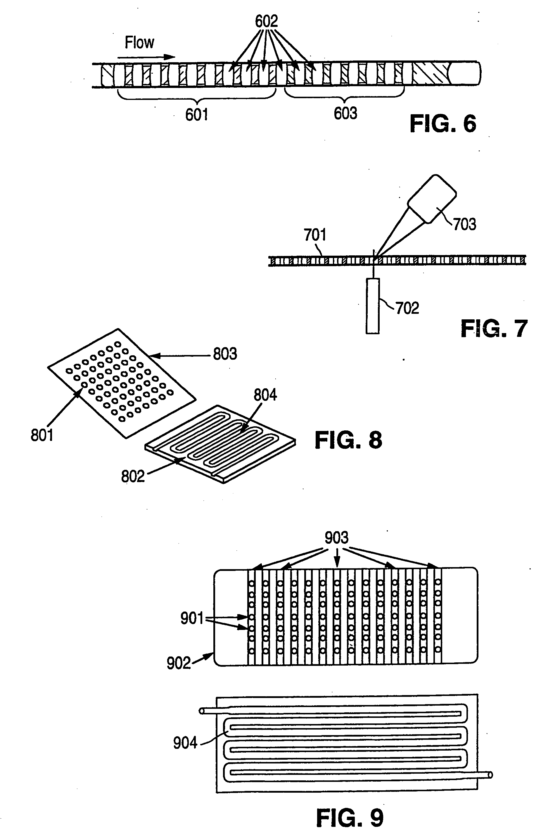
[0192] A capillary channel-based array hybridization system is illustrated in FIG. 8. The channel substrate 802 is composed of molded PDMS (polydimethylsiloxane) material, which can be molded with precise detail and which provides a surface readily sealed against the planar cover element (coverplate) 803. The channel 804 has a half-circular cross section. To minimize the amount of target analyte required for analysis and to minimize the distances through which target analytes must diffuse to reach binding partners, the channel has an internal diameter of 100 μm and a total length of 1 m. The channel is folded 100 times, the distance between the center of one channel segment and the center of an adjacent channel sequence is 400 μm, and the channel substrate is 4 cm×10 cm.

[0193] The coverplate is glass. Nucleic acid binding partners 801 are printed on the coverplate with using a robotic arrayer robot conventionally used for production of sta...

example 2

Capillary-Based Array Electrophoretic Hybridization System

[0195] Referring to FIG. 9, a device having the basic configuration described in Example 1 has nucleic acid binding partners 901 printed in a 2-dimensional array on a glass coverplate 902 on top of titanium-platinum electrodes 903. The electrodes 903 underlie a column of different binding partner locations in the 2-dimensional array. Each column of different binding partner locations has a long axis that is generally perpendicular to the longitudinal axis of each straight segment of the channel 904. To protect the nucleic acids from electrolysis products formed at the electrodes, the coverplate surface, including the conducting strips, are coated with a permeation layer comprised of 2% glyoxal agarose and 1 mg / ml streptavidin mixture. The nucleic acid binding partners are synthesized with a biotin attached to one end. Once the binding partners are deposited on the permeation layer, avidin / biotin binding affixes the nucleic a...


PUM


Abstract

The invention provides methods and devices for detecting the presence of one or more target analytes in a sample employing a channel having affixed therein one or more binding partners for each target analyte. Assays are carried out by transporting the sample through the channel to each successive binding partner so that target analyte present in said sample binds to the corresponding binding partner. The sample is then transported beyond the binding partner(s), followed by detection of any target analyte bound to each binding partner. In one embodiment, binding efficiency is increased by the use of segmented transport, wherein a first bolus or bubble of a fluid that is immiscible with the sample precedes the sample during transport and a second bolus or bubble of a fluid that is immiscible with the sample follows the sample. Many configurations are possible for the device of the invention. A preferred device includes: a substrate with a channel formed in its surface, and a cover element that overlies and seals the channel. Binding partner(s) are affixed to the surface of the cover element facing the channel lumen.

Description

CROSS REFERENCES TO RELATED APPLICATIONS [0001] This application is a divisional of and claims the benefit of U.S. application Ser. No. 10 / 960,224, filed Oct. 6, 2004, which is a divisional of U.S. Ser. No. 10 / 418,384, filed Apr. 17, 2003, which is a divisional of U.S. Ser. No. 09 / 652,873, filed Aug. 31, 2000, the disclosures of which are incorporated by reference for all purposes.STATEMENT AS TO RIGHTS TO INVENTIONS MADE UNDER FEDERALLY SPONSORED RESEARCH AND DEVELOPMENT [0002] This invention was made with Government support under Grant No. CA58207, awarded by the National Institutes of Health. The Government may have certain rights in this invention.FIELD OF THE INVENTION [0003] This invention relates to the field of diagnostics. In particular this invention provides devices and methods that allow rapid detection and / or quantitation of multiple analytes. BACKGROUND OF THE INVENTION [0004] Tumors progress through the continuous accumulation of genetic and epigenetic changes that en...

Claims


Application Information

Patent Timeline
Patent Type & Authority Applications(United States)
IPC IPC(8): G01N33/537G01N33/53G01N33/543G01N33/558
CPCB01J19/0046Y10T436/117497B01J2219/00511B01J2219/0052B01J2219/00605B01J2219/0061B01J2219/00612B01J2219/00621B01J2219/00626B01J2219/00628B01J2219/0063B01J2219/00637B01J2219/00641B01J2219/00657B01J2219/00722B01L3/502784B01L2200/0673B01L2300/0636B01L2300/0816B01L2300/0838B01L2400/0406B01L2400/0415B01L2400/0421B01L2400/0487G01N33/558Y10S436/807B01J2219/00479
Inventor FULWYLER, MACK J.GRAY, JOE W.
Owner RGT UNIV OF CALIFORNIA
Why Eureka
Try Eureka