Multi-phase DC-DC converter and control circuit for multi-phase DC-DC converter

Active Publication Date: 2006-07-27
CYPRESS SEMICON CORP
View PDF3 Cites 28 Cited by
  • Summary
  • Abstract
  • Description
  • Claims
  • Application Information

AI Technical Summary

Benefits of technology

[0025] The separately-excited DC-DC converter 100 shown in FIG. 1 always operates at the same frequency, and has a characteristic that the ripple of its output voltage Vo is small. However, the DC-DC converter 100 has a time lag between when its load suddenly changes to when the output transistor T1 is turned on. Thus, the DC-DC converter 100 has a problem of poor responsiveness to a sudden change in the load. To solve this problem, the operating frequency of the DC

Problems solved by technology

Thus, the DC-DC converter 100 has a problem of poor responsiveness to a sudden change in the load.
However, if the switching cycle of the output transistor is further shortened, the operating efficiency of the output transistor decreases due to a gate capacity of the output transistor.
Thus, increasing the switching frequency of the out

Method used


Image

  • Multi-phase DC-DC converter and control circuit for multi-phase DC-DC converter
  • Multi-phase DC-DC converter and control circuit for multi-phase DC-DC converter
  • Multi-phase DC-DC converter and control circuit for multi-phase DC-DC converter

Examples


first embodiment

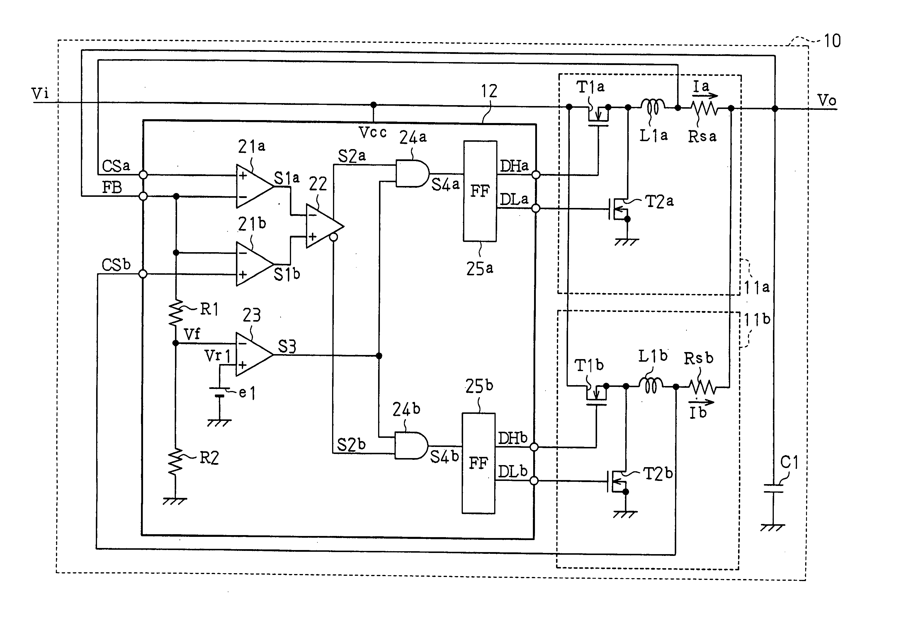
[0044]FIG. 4 is a schematic circuit diagram of a multi-phase DC-DC converter 10 according to the present invention.

[0045] The DC-DC converter 10 is a self-excited multi-phase DC-DC converter having two phases. The DC-DC converter 10 includes two converter units 11a and 11b, one control unit 12, and a smoothing capacitor C1.

[0046] The first converter unit 11a includes an output transistor T1a, a synchronous rectifier transistor T2a, a choke coil L1a, and a current detection resistor Rsa. The output transistor T1a is configured by an N-channel MOS transistor. The synchronous rectifier transistor T2a is configured by an N-channel MOS transistor. The output transistor T1a has a gate for receiving a control signal DHa from the control unit 12, a drain for receiving an input voltage Vi, and a source connected to the synchronous rectifier transistor T2a. The synchronous rectifier transistor T2a has a gate for receiving a control signal DLa from the control unit 12, a drain connected to th...

second embodiment

[0069]FIG. 5 is a schematic circuit diagram of a multi-phase DC-DC converter 30 according to the present invention.

[0070] The DC-DC converter 30 is a self-excited multi-phase DC-DC converter having two phases. The DC-DC converter 30 includes two converter units 11a and 11b, one control unit 32, and a smoothing capacitor C1.

[0071] The control unit 32 includes two voltage amplifiers 21a and 21b, a comparator 22, two voltage comparators 23a and 23b, two reference power supplies e1 and e2, two resistors R1 and R2, two AND circuits 24a and 24b, two one-shot flip-flop circuits (hereafter referred to as “FF circuits”) 25a and 25b, and two OR circuits 26a and 26b. The control unit 32 of the second embodiment has a configuration in which the voltage comparator 23b, the reference power supply e2, and the OR circuits 26a and 26b are added to the control unit 12 of the first embodiment.

[0072] The first voltage comparator 23a operates substantially in the same manner as the voltage comparator ...

third embodiment

[0079]FIG. 6 is a schematic circuit diagram of a multi-phase DC-DC converter 40 according to the present invention.

[0080] The DC-DC converter 40 is a self-excited multi-phase DC-DC converter having three phases. The DC-DC converter 40 includes three converter units 11a, 11b, and 11c, one control unit 42, and a smoothing capacitor C1.

[0081] Each of the converter units 11a to 11c has the same configuration. The first converter unit 11a includes an output transistor T1a, a synchronous rectifier transistor T2a, a choke coil L1a, and a current detection resistor Rsa. The output transistor T1a is configured by an N-channel MOS transistor. The synchronous rectifier transistor T2a is configured by an N-channel MOS transistor. The second converter unit 11b includes an output transistor T1b, a synchronous rectifier transistor T2b, a choke coil L1b, and a current detection resistor Rsb. The output transistor T1b is configured by an N-channel MOS transistor. The synchronous rectifier transisto...


PUM


Abstract

A self-excited multi-phase DC-DC converter having satisfactory responsiveness when its load suddenly changes. A control unit of the converter compares output currents of first and second converter units. Based on the comparison result, the control unit generates control signals to operate a converter unit through which a smaller output current flows. For example, when an output voltage of the converter decreases due to a sudden change in the load while the first converter unit is operating to supply current, the second converter unit through which a smaller output current flows is operated to increase the output voltage.

Description

CROSS-REFERENCE TO RELATED APPLICATIONS [0001] This application is based upon and claims the benefit of priority from the prior Japanese Patent Application No. 2005-020141, filed on Jan. 27, 2005, the entire contents of which are incorporated herein by reference. BACKGROUND OF THE INVENTION [0002] The present invention relates to a converter, and more particularly, to a multi-phase DC-DC converter and a control circuit for a multi-phase DC-DC converter. [0003] Japanese Laid-Open Patent Publication Nos. 2000-308337, 2002-044941, and 2003-284333 each describe an example of a conventional multi-phase DC-DC converter, in which a plurality of DC-DC converters are connected in parallel and each converter is operated at a different switch timing (phase). [0004] Methods for controlling a DC-DC converter include separate-excitation and self-excitation. With separate-excitation, a DC-DC converter performs a switching operation in synchronization with a clock signal (separately-excited DC-DC c...

Claims


Application Information

Patent Timeline
IPC IPC(8): G05F1/618G05F1/56
CPCH02M3/1584
Inventor HASEGAWA, MORIHITOOZAWA, HIDEKIYO
Owner CYPRESS SEMICON CORP
Why Eureka
Try Eureka