Soldering method and apparatus

Inactive Publication Date: 2006-08-03
FUJITSU LTD
View PDF13 Cites 3 Cited by
  • Summary
  • Abstract
  • Description
  • Claims
  • Application Information

AI Technical Summary

Benefits of technology

[0026] Details of the soldering apparatus are basically identical to those of the soldering method according to the present invention. In other words, each step in the soldering method is provided as each unit. According to the present invention, for example, respective pads of a suspension of a head gimbals assembly in a hard disk drive and a slider can be finely jointed by giving an external force to a solder ball and mechanically deforming the same immediately before the jointing to break an oxide film of the surface thereof and by rapidly heating the joint unit through light energy irradiation instead of using a flux in a state where excellent solder we

Problems solved by technology

However, since the Au ultrasonic jointing method applies the mechanical ultrasonic vibration to joint the joint unit, there are problems that a residual stress remains on the jointing and the jointing may release across the ages and that material and equipment costs are high.
However, soldering connection generally requires to use a flux for securing solder wettability.
If the cleansing is not complete, there is a possibility that a failure such as head crash due to the flux residuals occurs, and it is necessary to construct a cleansing process having a sufficient margin.
However, the conventional fluxless soldering method has the following problems.
In the soldering method in patent reference 1, there are various problems that the pre-step of previously forming the solder bumps in the end pad of the suspension and the contact pad of the slider, respectively, is required, that equipment cost of th

Method used


Image

  • Soldering method and apparatus
  • Soldering method and apparatus
  • Soldering method and apparatus

Examples


Example

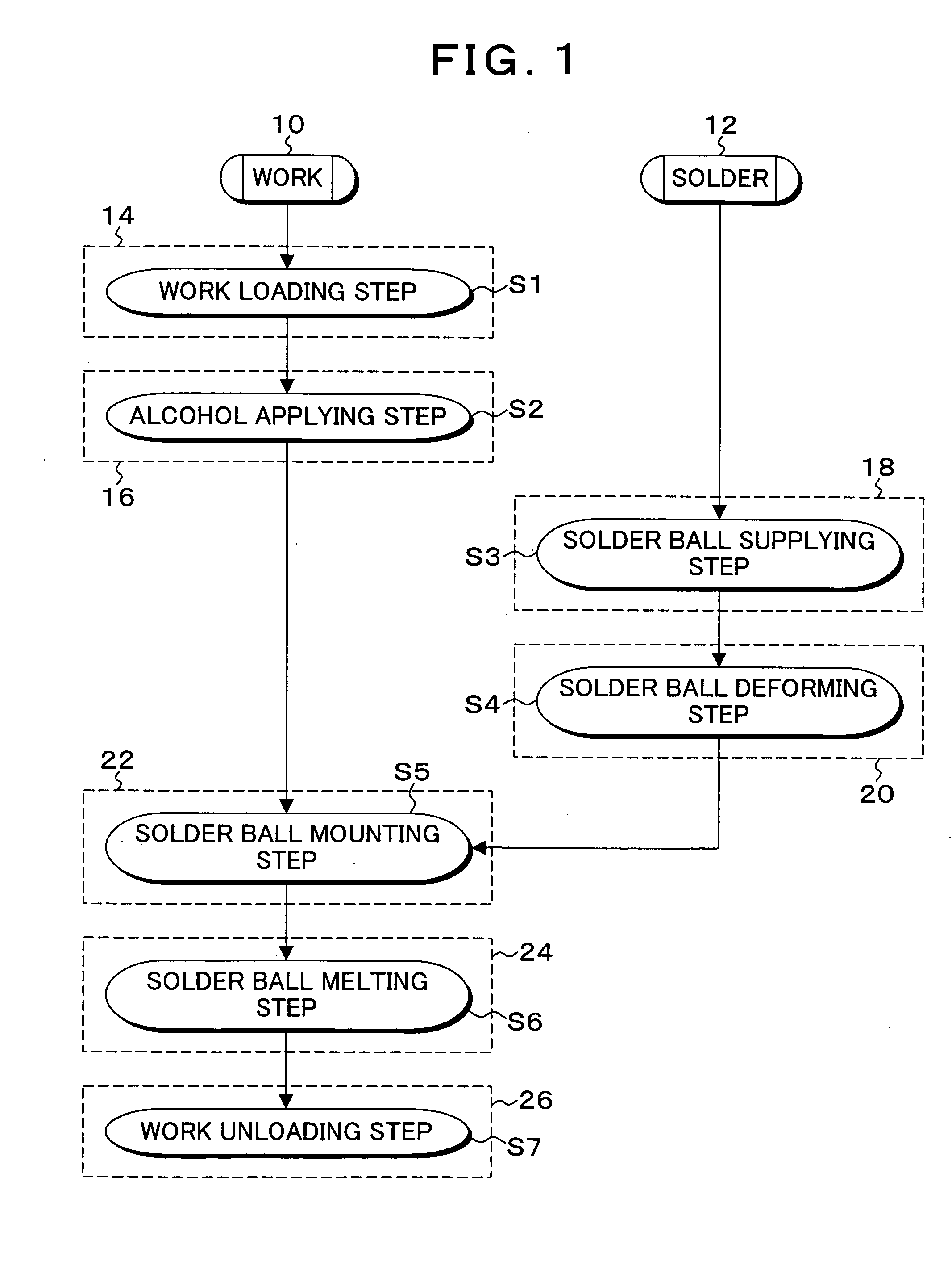
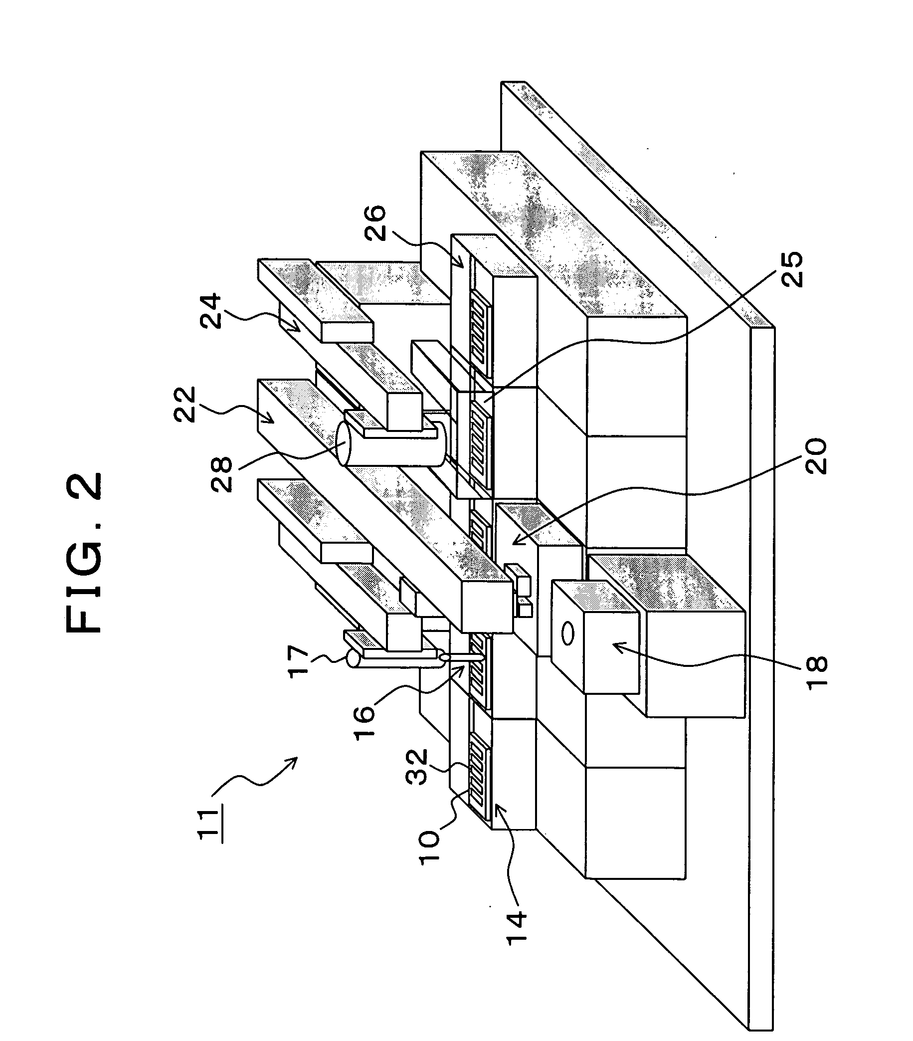
[0035]FIG. 1 is an explanatory diagram of processing steps in a soldering method according to the present invention. In FIG. 1, the soldering method according to the present invention is constituted of a work loading step S1, an alcohol applying step S2, a solder ball supplying step S3, a solder ball deforming step S4, a solder ball mounting step S5, a solder ball melting step S6, and a work unloading step S7 in the order of the steps. There are provided, as units corresponding to these steps, a loading unit 14, an alcohol applying unit 16, a solder ball supplying unit 18, a solder ball deforming unit 20, a solder ball mounting unit 22, a solder ball melting unit 24, and an unloading unit 26, and the combination of these units constitutes a soldering apparatus according to the present invention. In the work loading step S1, the loading unit 14 uses roller carrying to load a work in the soldering apparatus. In the present invention, as will be clear in the later explanation, there is...


PUM

PropertyMeasurementUnit
Melting pointaaaaaaaaaa
Boiling pointaaaaaaaaaa
Energyaaaaaaaaaa

Abstract

There are provided a solder ball deforming step of mechanically deforming a ball to break an oxide film of a surface thereof and to expose a nonoxide surface and a solder melting step of heating and melting the deformed solder ball through energy irradiation in a state where the deformed solder ball is mounted on joint units of a loaded work. The solder ball deforming step mechanically deforms the solder ball to form at least two orthogonal contact surfaces in contact with the joint surfaces of the joint units.

Description

[0001] This application is a priority based on prior application No. JP 2005-22775, filed Jan. 31, 2005, in Japan. BACKGROUND OF THE INVENTION [0002] 1. Field of the Invention [0003] The present invention relates to a soldering method and apparatus for soldering works by using a fine solder ball, and particularly to a soldering method and apparatus for soldering works by using a low-melting-point solder ball instead of using a flux. [0004] 2. Description of the Related Arts [0005] Conventionally, a head gimbals assembly which is a constituent of a hard disk mounts thereon a slider which mounts a head on a suspension mounted on a tip of an arm driven by a voice coil motor, and an Au—Au ultrasonic jointing method using platinum is used for electrically jointing and fixing the suspension and the slider. In the Au ultrasonic jointing method, a head called capillary is directly pressed on an Au jointing potion and a mechanical ultrasonic vibration is applied thereto to joint the same. Ho...

Claims


Application Information

Patent Timeline
IPC IPC(8): B23K1/005
CPCB23K1/206B23K3/0623H05K3/3442H05K3/3478H05K2201/0382H05K2201/10727H05K2203/0195H05K2203/041H05K2203/0465Y02P70/50G11B21/21G11B5/60G11B5/127
Inventor TANAKA, HISAOFUJII, MASANAOOKADA, TORUIIDA, SUSUMUYAMANISHI, HIROKAZUNODA, YUTAKA
Owner FUJITSU LTD
Why Eureka
Try Eureka