
Adjustable start-up circuit for switching regulators

a start-up circuit and switching regulator technology, applied in the field of switching regulators, can solve the problems of wasting wasting a long time to simulate and verify the conventional switching regulator, and a large amount of time until the start-up time, etc., to achieve the effect of improving the start-up time very fast, reducing the cost of operation, and improving the controllability of the initial level

Inactive Publication Date: 2006-08-03
PARK SANGBEOM
View PDF7 Cites 11 Cited by
  • Summary
  • Abstract
  • Description
  • Claims
  • Application Information

AI Technical Summary

Benefits of technology

[0007] Consequently, all adjustable start-up circuits provide a significant reduction in the difference between the initial output voltage level and the expected output voltage level in order to overcome serious drawbacks simultaneously. The adjustable start-up time of the present invention enables all systems to be managed in terms of power, stand-by time, and start-up time. The present invention provides five different embodiments which achieve a drastic improvement in a very fast start-up time, start-up time controllability, adjustable initial level, performance, time-to-market, power consumption, power and time management, efficiency, cost, and design time.

Problems solved by technology

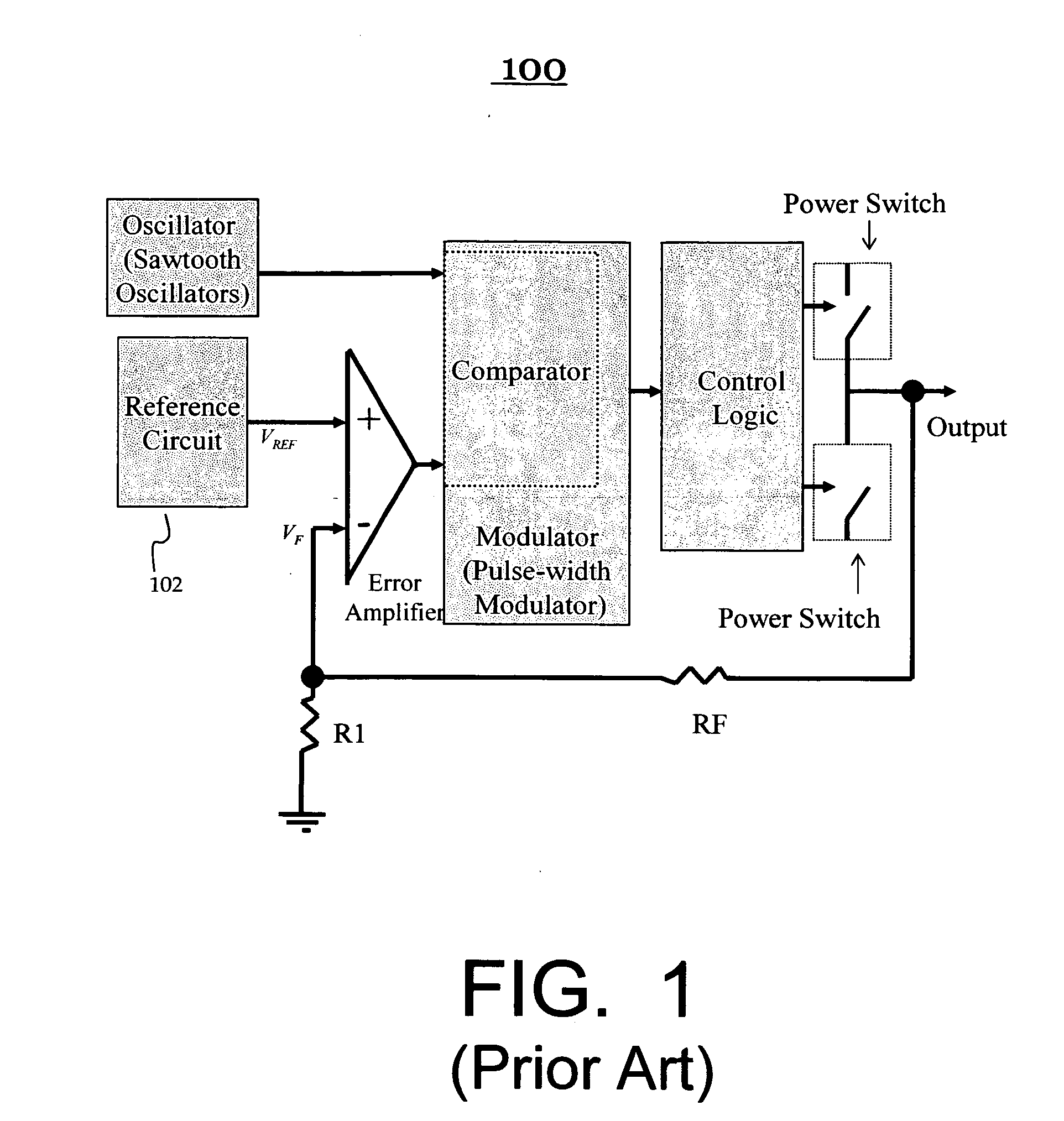
However, it takes a vast amount of time until the output voltage level reaches the equilibrium from an initial condition after the switching regulator of Prior Art FIG. 1 starts.
Therefore, power and time are consumed until the switching regulator's output voltage level reaches the equilibrium.
In addition, it takes a long time to simulate and verify the conventional switching regulator 100 before fabrication since its simulation time is absolutely proportional to time that is required the switching regulator's output voltage level to reach the equilibrium.
Hence, this long simulation adds additional cost and serious bottleneck to design time-to-market.
In other words, the slow start-up of the switching regulator increases design simulation time.
For these reasons, the conventional switching regulator 100 of Prior Art FIG. 1 is very inefficient to implement in system-on-chip (SOC) or integrated circuit (IC).

Method used


Image

  • Adjustable start-up circuit for switching regulators
  • Adjustable start-up circuit for switching regulators
  • Adjustable start-up circuit for switching regulators

Examples


Embodiment Construction

[0016] In the following detailed description of the present invention, five types of the adjustable start-up circuits, numerous specific details are set forth in order to provide a thorough understanding of the present invention. However, it will be obvious to one skilled in the art that the present invention may be practiced without these specific details. In other instances, well known methods, procedures, CMOS digital gates, components, and metal-oxide-semiconductor field-effect transistor (MOSFET) device physics have not been described in detail so as not to unnecessarily obscure aspects of the present invention.

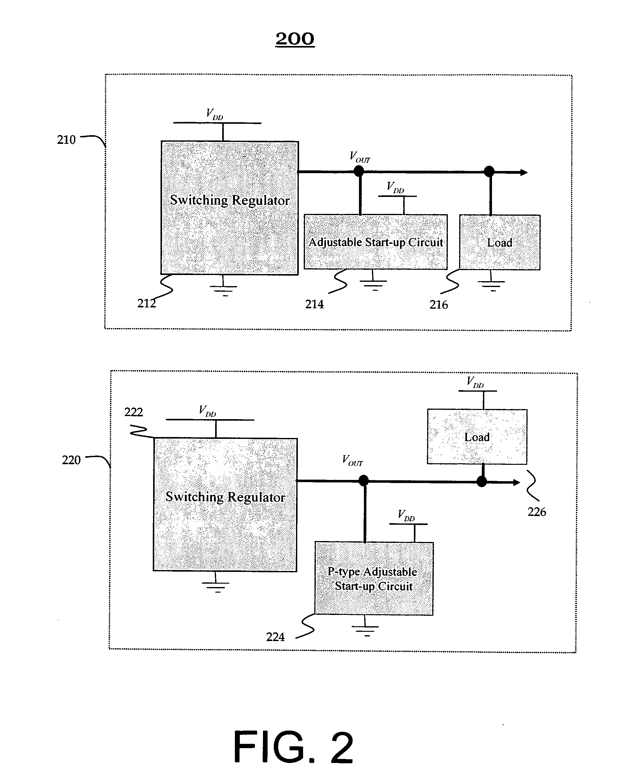
[0017]FIG. 2 illustrates two types of the adjustable start-up circuits for switching regulators in accordance with the present invention. One type of the adjustable start-up circuit is applied for switching regulators driving a load 216 connected between VOUT and ground, as seen in the switching regulator system 210 shown in FIG. 2. The other type of the adjustable star...


PUM


Abstract

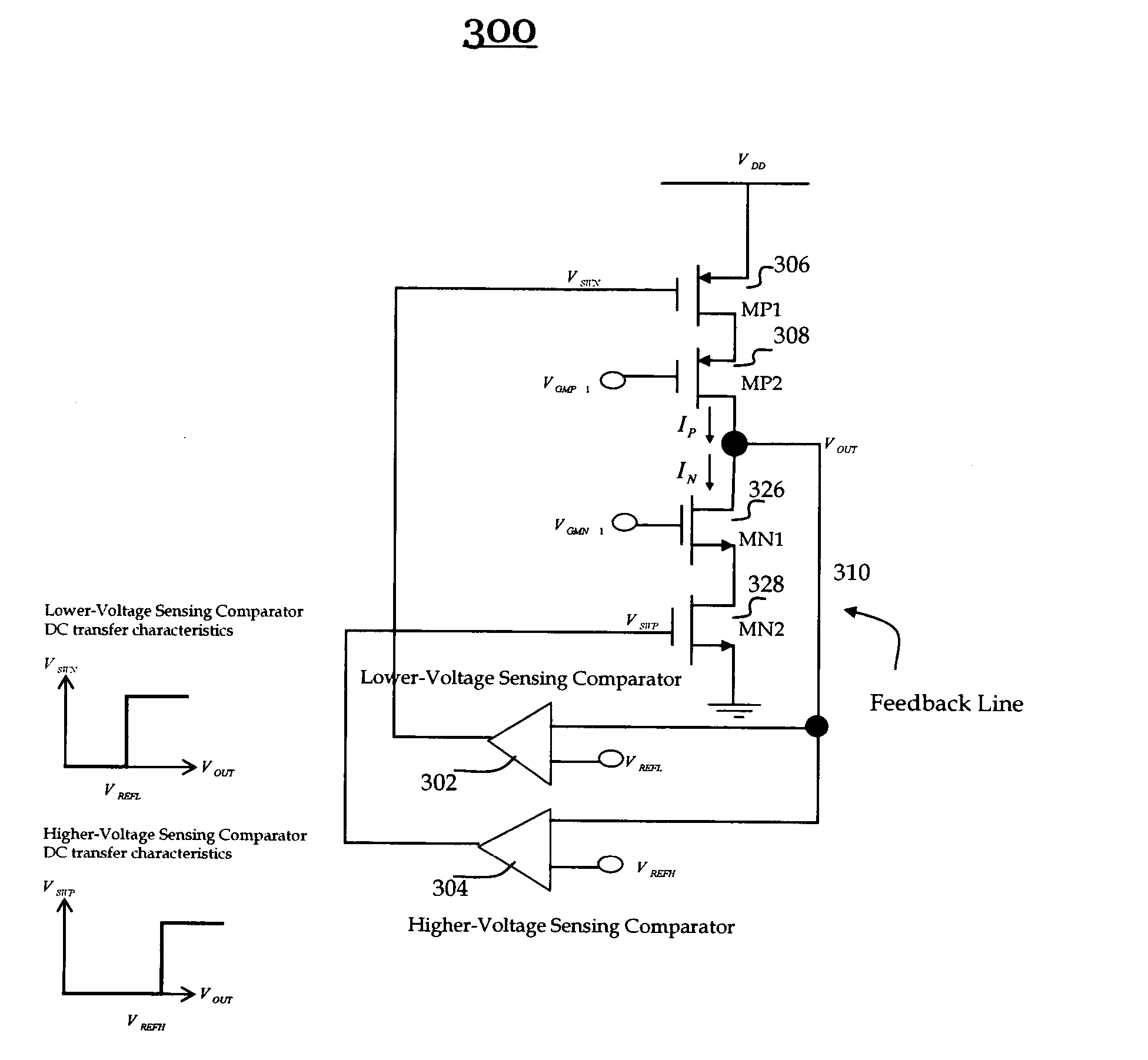
The adjustable start-up circuits basically include a sensor, a reference voltage, two stacked PMOS transistors, two stacked NMOS transistors, and a feedback line. The sensor compares a feedback voltage with a reference voltage. If the sensing voltage does not reach the reference voltage, the output voltage of the sensor turns on the corresponding transistor, which provides a current to its output until the voltage at feedback reaches the reference voltage. The time to reach the expected output voltage level at a load is simply equal to the charge stored at the load divided by the current, which can be scaled by a device aspect ratio of the transistor. Consequently, all adjustable start-up circuits provide an adjustable initial output voltage level closer to the output voltage level that reaches the equilibrium according to schedule. In addition, the output voltage level is varied by changing the reference voltage level.

Description

FIELD OF THE INVENTION [0001] The present invention relates to the field of switching regulator and more particularly to adjustable start-up circuit for switching regulators. BACKGROUND ART [0002] Switching regulator is a vitally important device. Switching regulators are building blocks used extensively in power systems, industry, motor, communication, networks, digital systems, consumer electronics, computers, and any other fields that require high efficient voltage regulating functions. [0003] Switching regulators (i.e., DC-TO-DC converters) can provide output voltages which can be less than, greater than, or of opposite polarity to the input voltage. Prior Art FIG. 1 illustrates a basic architecture of a conventional switching regulator 100. The conventional switching regulator 100 basically consists of an oscillator, a reference circuit 102, an error amplifier, a modulator, resistors, and a control logic circuit. It is noted that the modulator includes a comparator. Control tec...

Claims


Application Information

Patent Timeline
IPC IPC(8): H03L7/00
CPCH02M1/36
Inventor PARK, SANGBEOM
Owner PARK SANGBEOM
Learn More