
Fuel cell, electrode material for fuel cell and method for producing same

Inactive Publication Date: 2006-08-03
SHINANO KENSHI
View PDF0 Cites 6 Cited by
  • Summary
  • Abstract
  • Description
  • Claims
  • Application Information

AI Technical Summary

Benefits of technology

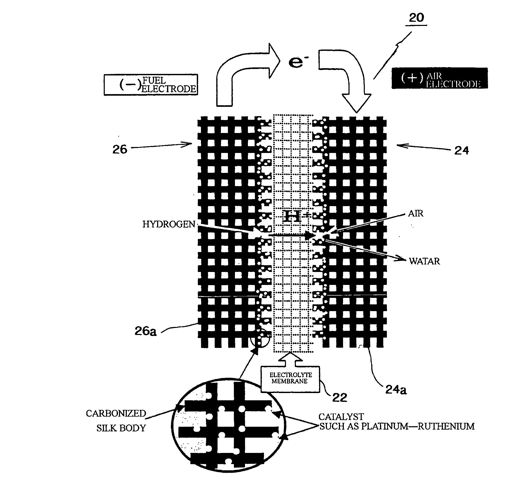
[0035] According to the present invention, in the carbonized silk body, interspaces exist between single yarns or twisted yarns, which are constituted by fibers, or fibers constituting unwoven cloth, and permeability and diffusivity of fuel and a gas are improved so that power generation efficiency of the fuel cell can be improved. Further, contact efficiency of the fuel and the gas with the catalyst supported by the carbonized silk body or the catalyst layer formed in the carbonized silk body can be improved, so that catalytic function can be well brought out and an electromotive force can be stably generated.
[0036] By improving the contact efficiency of the gas with the catalyst metal, an amount of the catalyst metal can be reduced so that the production cost can be reduced.
[0037] Further, since the carbonized silk body is not deteriorated at high temperature, a span of life of the fuel cell can be made longer.

Problems solved by technology

The catalyst layers 14c and 16c, in which the carbon powders supporting the catalyst metals are applied to the carbon cloth (or carbon paper), have poor air-permeability so that the catalyst metals cannot work well.
Further, a large amount of carbon powders and a large amount of catalyst metals are required, so that production cost of the cell element must be increased.
Carbon paper made from carbon fibers has poor flexibility.
Carbon cloth has enough flexibility and toughness, but if fuel permeability and catalyst supportability are optimized, the production cost must be further increased, namely the carbon cloth has a problem of impractical.
Their amounts are very small, but they are harmful substances irritating noses and lungs.

Method used


Image

  • Fuel cell, electrode material for fuel cell and method for producing same
  • Fuel cell, electrode material for fuel cell and method for producing same
  • Fuel cell, electrode material for fuel cell and method for producing same

Examples


example 1

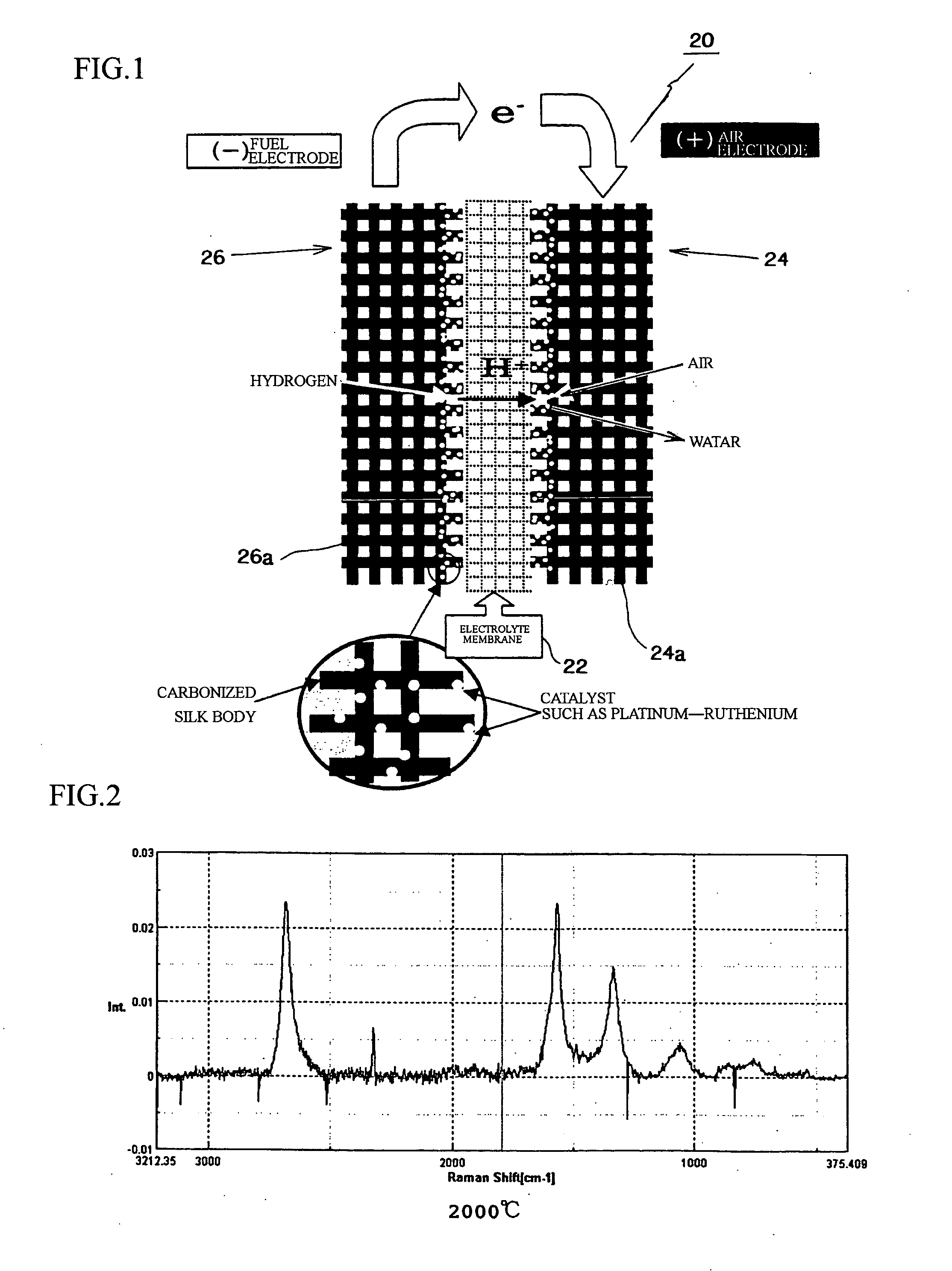
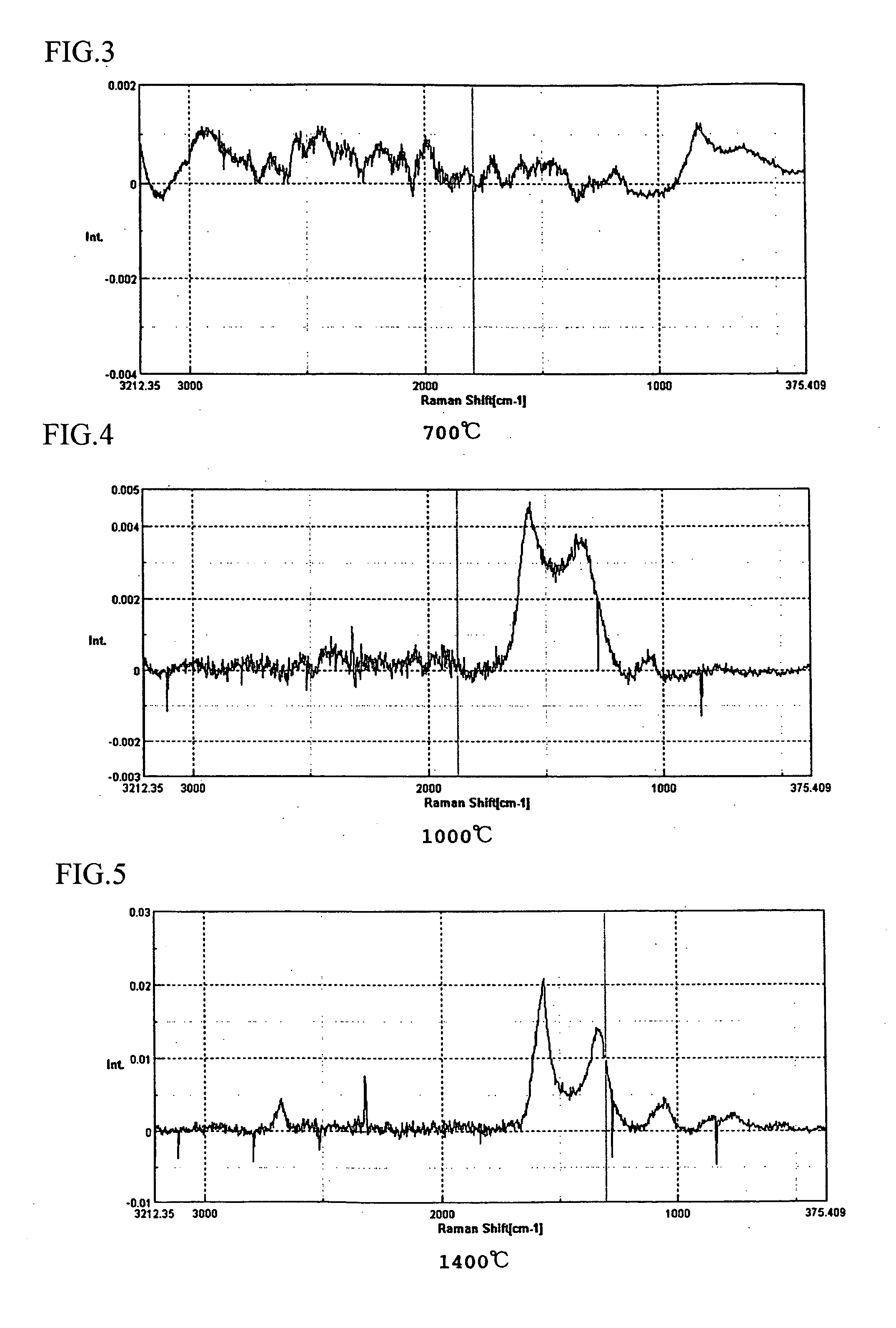
[0092] A silk material was heated in a nitrogen gas atmosphere until reaching first temperature (450° C.) with low temperature rising rate of 50° C. / hour, then the material was burned at the first temperature for five hours as the primary burning. Next, the burned material was once cooled until reaching the room temperature, then the material was reheated in the nitrogen gas atmosphere until reaching second temperature (1,000° C.) with low temperature rising rate of 50° C. / hour, then the material was burned at the second temperature for five hours as the secondary burning. Further, the burned material was cooled until reaching the room temperature, then the material was reheated in the nitrogen gas atmosphere until reaching third temperature (2,000° C. or final burning temperature) with low temperature rising rate of 50° C. / hour, then the material was burned at the third temperature for five hours as the third burning. Then, the burned material was cooled, so that the carbonized sil...

example 2

[0095] A silk material was heated in a nitrogen gas atmosphere until reaching first temperature (450° C.) with low temperature rising rate of 50° C. / hour, then the material was burned at the first temperature for five hours as the primary burning. Next, the burned material was once cooled until reaching the room temperature, then the material was reheated in the nitrogen gas atmosphere until reaching second temperature (1,000° C.) with low temperature rising rate of 50° C. / hour, then the material was burned at the second temperature for five hours as the secondary burning. Further, the burned material was cooled until reaching the room temperature, then the material was reheated in the nitrogen gas atmosphere until reaching third temperature (2,000° C. or final burning temperature) with low temperature rising rate of 50° C. / hour, then the material was burned at the third temperature for five hours as the third burning. Then, the burned material was cooled, so that the carbonized sil...

example 3

[0097] A silk material was burned in a nitrogen gas atmosphere at final burning temperature of 1,400° C. as well as the above described examples, then the burned material was cooled until reaching the room temperature so as to obtain a carbonized silk body. Carbon powders, which support the catalyst metals, were mixed with a nafion solution or the like so as to form into paste, the paste was applied to the carbonized silk body, and the carbonized silk body was heated so as to volatilize the solution, so that a catalyst layer was formed on the carbonized silk body. The carbonized silk body having the catalyst layer was used as a diffusion layer, and a nafion electrolyte membrane was inserted therein and hot-pressed, so that an MEA (membrane-electrode adelphus ???), which was a constitutional unit of a fuel cell, was formed. Measured output characteristics of the MEA (membrane-electrode assembly) are shown in FIGS. 8 and 9. FIG. 8 shows I-V characteristics; FIG. 9 shows I-W characteri...


PUM


Abstract

The present invention provides a fuel cell, which enables to reduce production cost and has excellent cell characteristics. The fuel cell comprises a cell element 20, in which a cathode layer 24 is formed on one side of an electrolyte membrane 22 and an anode layer 26 is formed on the other side thereof, and generates an electromotive force through oxidation-reduction reaction, which occurs via the electrolyte membrane 22, between a fuel such as methane and an oxidant such as oxygen supplied, the fuel cell is characterized in that at least one of the cathode layer 24 and the anode layer 26 contains an electrode material 24a, 26b which is composed of a carbonized silk body obtained by burning a silk material and a catalyst metal supported by the carbonized silk body.

Description

FIELD OF TECHNOLOGY [0001] The present invention relates to a fuel cell, an electrode material for the fuel cell and a method for producing the electrode material. BACKGROUND TECHNOLOGY [0002] An example of a cell element 10 of a conventional fuel cell is shown in FIG. 7. [0003] A symbol 12 stands for an electrolyte membrane 12. In the cell element 10, a cathode layer 14 is formed on one side of the electrolyte membrane 12 and an anode layer 16 (a fuel electrode) is on the other side thereof. Electrode plates, not shown, are provided to the cathode layer 14 and the anode layer 16, and cables (not shown) are connected to the both electrode plates. [0004] A fuel and oxygen or a gas including oxygen (an oxidant) are supplied to the cell element 10, so that oxidation-reduction reaction occurs via the electrolyte membrane 12 and an electromotive force is generated. [0005] Electrode materials 14a and 16a, which support catalyst metals for accelerating electrode reaction, are provided to t...

Claims


Application Information

Patent Timeline
IPC IPC(8): H01M4/86H01M4/88H01M4/96H01M4/92H01M8/02H01M8/10
CPCH01M4/881H01M4/92H01M4/926H01M8/1004Y02E60/521Y02E60/50Y02P70/50
Inventor HASHIZUME, HITOSHISHIMIZU, MAKOTOYAWATA, TOMIO
Owner SHINANO KENSHI
Learn More