Method for stepper motor position referencing

a stepper motor and position reference technology, applied in the direction of electric programme control, dynamo-electric converter control, instruments, etc., can solve the problems of increasing the current step response and the tendency of the instrument stepper motor to kick back off of the hard stop, so as to increase the positioning accuracy, less signal to noise, and high signal to noise ratio

Active Publication Date: 2006-08-10
TEXAS INSTR INC
View PDF12 Cites 53 Cited by
  • Summary
  • Abstract
  • Description
  • Claims
  • Application Information

AI Technical Summary

Benefits of technology

[0010] This invention actually detects the last point of travel of a stepper motor before it stalls. In this case a stall indicates loss of synchronism. The prior methods detect a change in back-EMF after the motor stalls. An instrumentation stepper motor has a tendency to kick back off of the hard stop after it stalls. The invention increases positioning accuracy by eliminating the problems associated with motor kick back. When sensing the back-EMF in the undriven coil of a stepper sequence, the relative phase of the back-EMF may present additional sensitivities due to uncertainty whether the voltage is negative going or positive going. The former method uses a single voltage measurement attempting to determine changes as small as 10 millivolts. This requires a high signal to noise ratio. This invention uses multiple measurements to ensure robustness and requires less signal to noise.
[0011] This invention uses the fact that in most stepper systems there is a short time in which the system load increases before motor stall and lose of synchronism. This load increase may be due reduction gearing, drive belts, compression in fittings or the equivalent. This invention needs a least one step pulse in which the load is increased. A typical instrumentation stepper motor with built in reduction gear, may have 3 or 4 pulses during which the load is increasing. This invention examines the current step response of the motor. During normal operation before a load increase, the current step responses are fairly consistent from step to step within a given current direction and phase. The direction and phase of the current step response can change due to coil parameter changes, FET parameter changes and other factors. This invention uses the step to step variation as a measure. As the load increases, the current step response becomes more critically damped. This results in a more square step response with less overshoot, less undershoot and less ringing. As the load increases, the current will initially decrease from the previous step due to the slowing of the system and eventually increase once the max load pulse is instantiated. The combination of these factors provides a robust measure of increased load and thus a solid, repeatable reference point in a system. The motor velocity and the various measures can be calibrated so that the motor is halted before the motor loses synchronism.

Problems solved by technology

An instrumentation stepper motor has a tendency to kick back off of the hard stop after it stalls.
As the load increases, the current step response becomes more critically damped.

Method used


Image

  • Method for stepper motor position referencing
  • Method for stepper motor position referencing
  • Method for stepper motor position referencing

Examples


Embodiment Construction

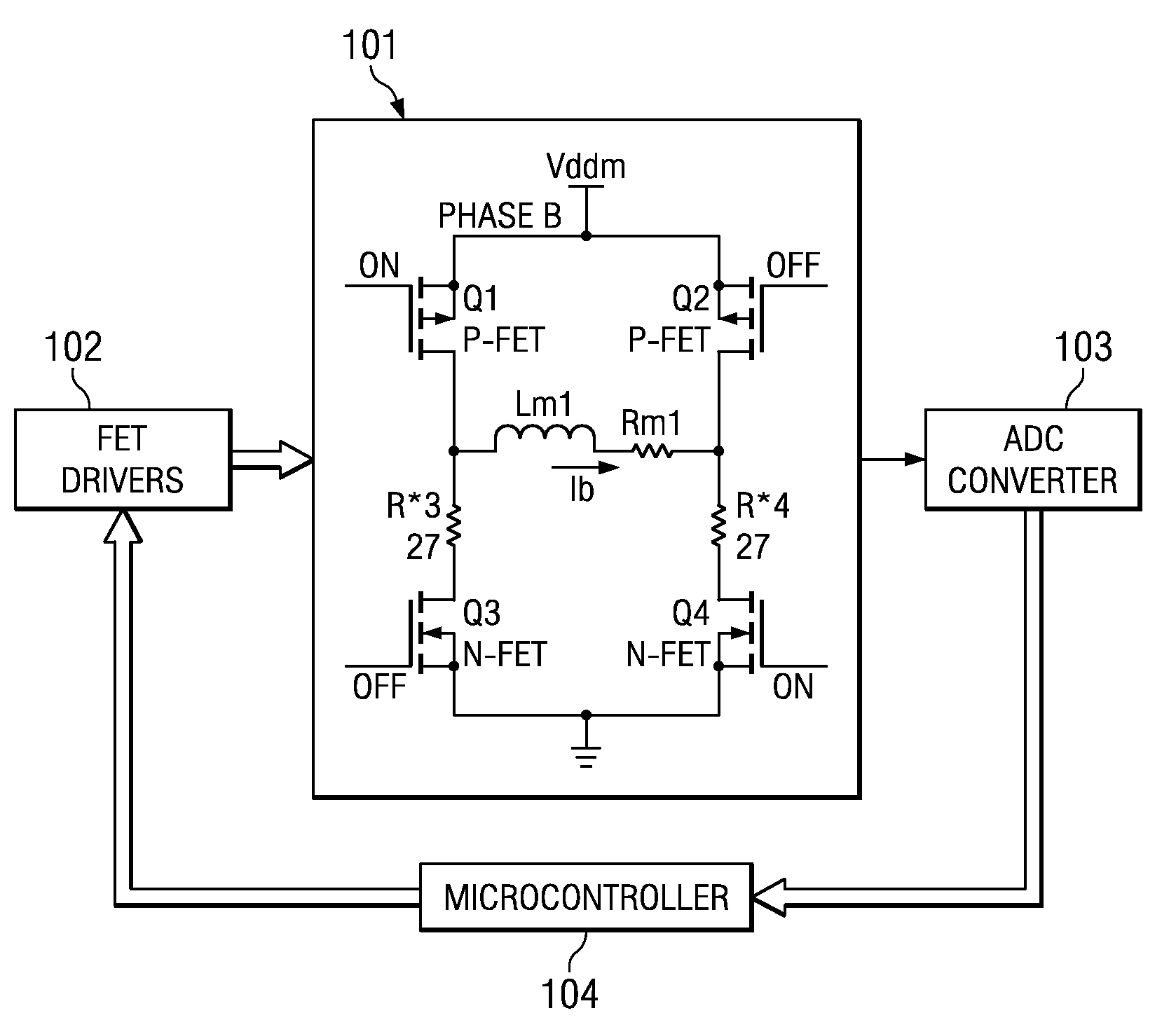
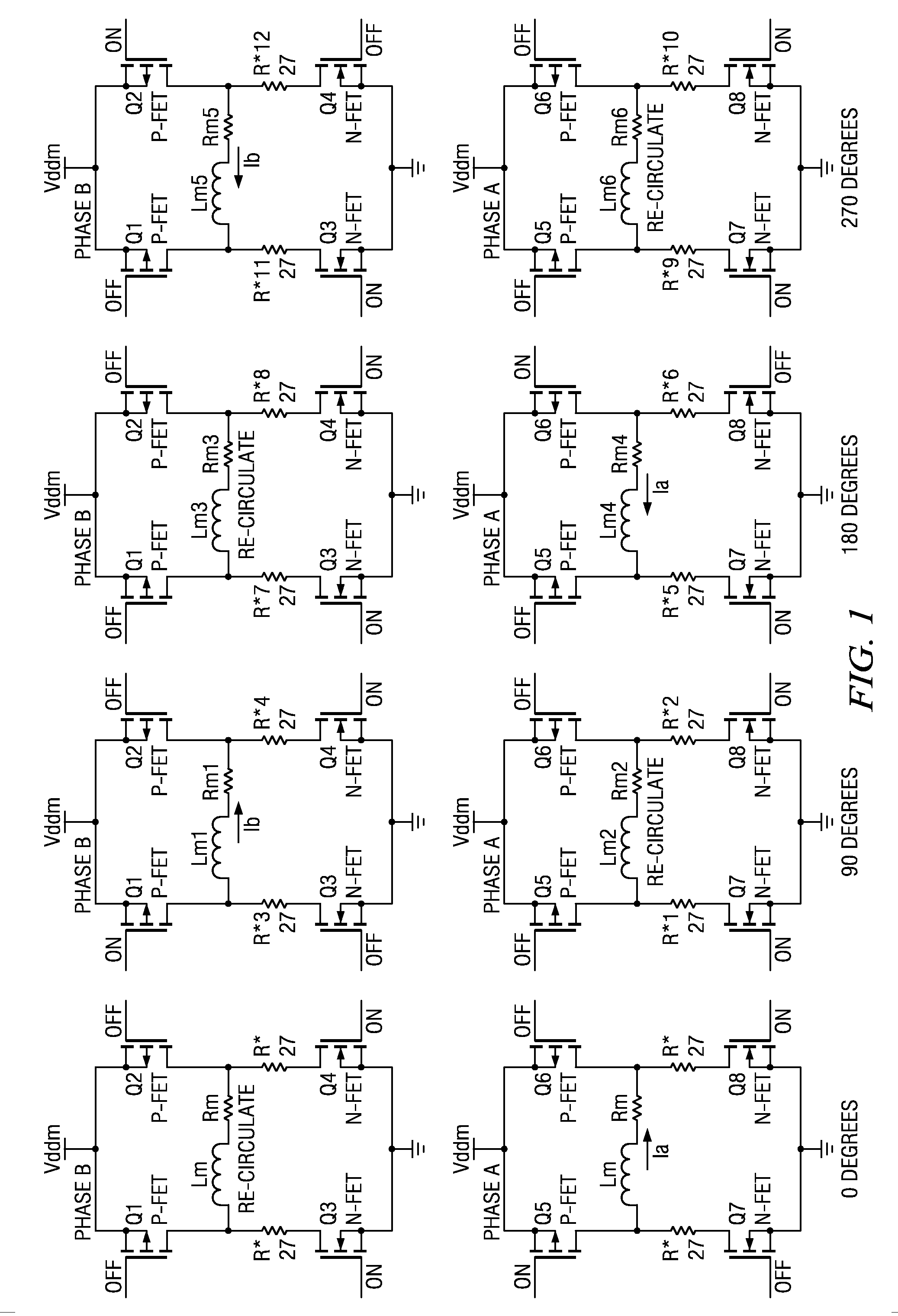
[0017] A stepper motor control system can be driven in many different fashions. For the explanation of this invention, the standard H-bridge architecture will be described with full stepping mode. A stepper motor can be driven in full step mode as shown in FIG. 1. There are four step states in this mode (0°, 90°, 180°, 270°), which correspond to the electrical angle of the motor within a given pole pair. These step states will be used as references in this description.

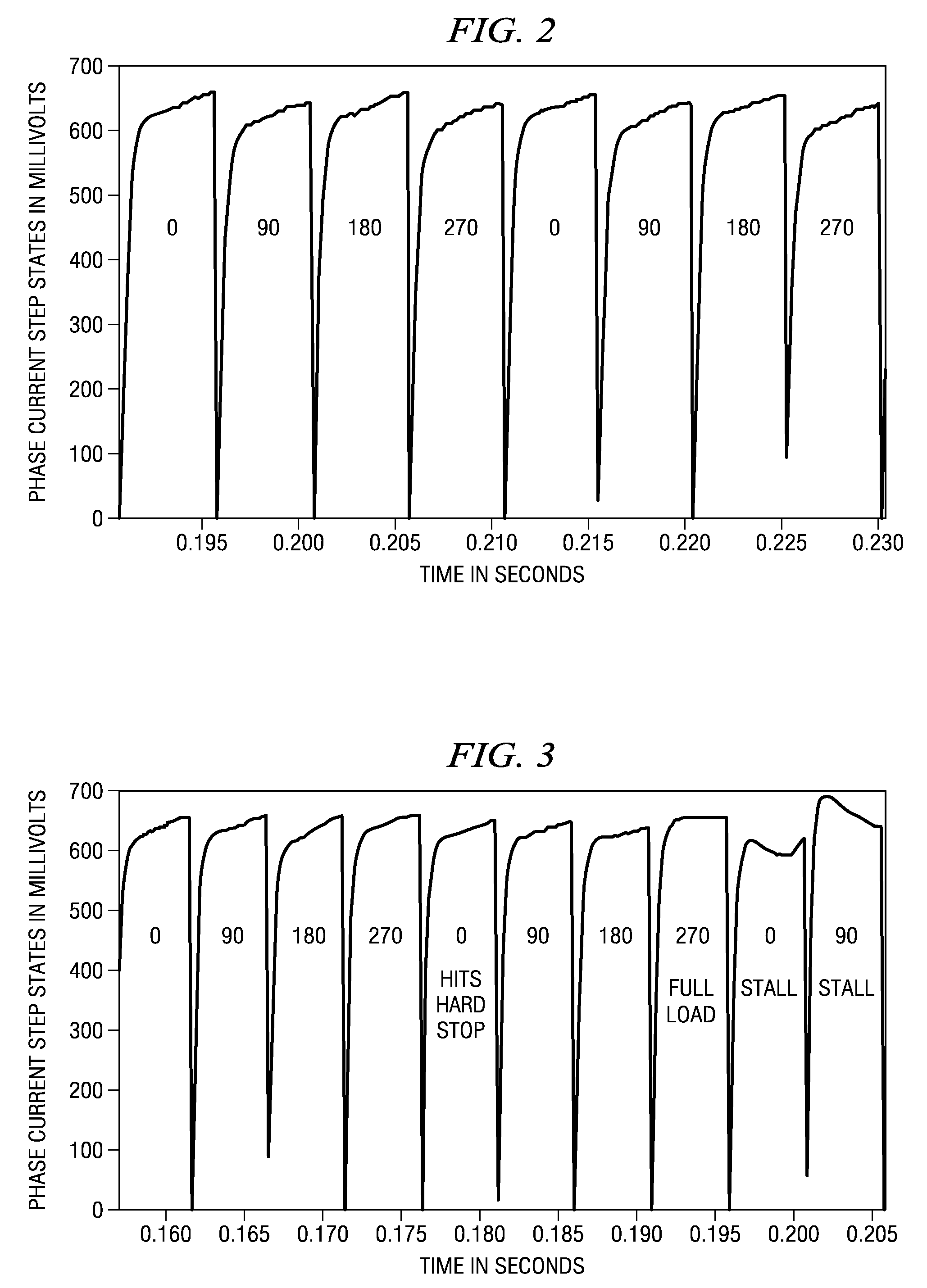
[0018] While the motor is full stepping at a constant velocity with the steps changing state at a fixed rate, the step response to step response variance between step states will be relatively low. For instance, the step response during step state=0° will be similar to four steps prior, the last time the motor was at this step state. FIG. 2 depicts the constant step to step nature as described. In a system that exhibits a gradual increase of load due to reduction gearing, belt slack, fitting compression and the like, ...


PUM


Abstract

A method for referencing a polyphase stepper motor by monitoring the current step response in at least one driven phase is presented. The coil current step response is compared to past step responses in order to determine when an increase in or maximum load is present. A combination of step to step variance, step response variance from mean current magnitude, and average current magnitude variance, as well as other measures can be combined to create an algorithm output. The output is compared to a pre-determined threshold and if the value is greater than the threshold, the motor is commanded to halt its position, which remains magnetically synchronous. This position is then used as a reference point to zero, or to home the motor.

Description

CLAIM OF PRIORITY [0001] This application claims priority under 35 U.S.C. 119(e)(1) to U.S. Provisional Application No. 60 / 648,832 filed Jan. 31, 2005.TECHNICAL FIELD OF THE INVENTION [0002] The technical field of this invention is stepper motors which are position referenced to a fixed position such as a zero point or home using of a mechanic hard stop internal or external to the motor. BACKGROUND OF THE INVENTION [0003] There are many applications in which stepper motors need to be referenced to a fixed position such as a zero point or home position. These include instrumentation gauges used in automotive clusters, steppers used in medical equipment and positioning steppers used in industrial controls. [0004] Stepper motors are typically run in an open loop position mode, where there is no position feedback from the motor shaft, the system output shaft or otherwise to determine the position of the motor. A stepper motor in this configuration is assumed to be magnetically synchrono...

Claims


Application Information

Patent Timeline
Patent Type & Authority Applications(United States)
IPC IPC(8): G05B19/40
CPCG05B19/40H02P8/08G05B2219/41326G05B2219/41101
Inventor BEST, ERIC P.
Owner TEXAS INSTR INC
Why Eureka
Try Eureka