Signal transmission system and signal transmission method

a transmission system and signal technology, applied in the direction of radio transmission, power management, electrical equipment, etc., can solve the problems of large interference, inability to perform power control in radio communication systems, and mobile terminals operating under different radio communication systems are not necessarily always located, so as to achieve the effect of increasing the noise level

Inactive Publication Date: 2006-08-10
FUJITSU LTD
View PDF19 Cites 25 Cited by
  • Summary
  • Abstract
  • Description
  • Claims
  • Application Information

AI Technical Summary

Benefits of technology

[0028] According to the present invention, increase of a noise level measured in the radio base station due to mixing of a signal from the second radio communication system can be reduced in a signal transmission system for transmitting an UP LINK signal received by an antenna shared by the first radio communication system and the second radio communication system to the radio base station of the first radio communication system.

Problems solved by technology

However, plural mobile terminals operating under different radio communication systems are not necessarily always located nearly equidistant from the antenna.
In the W-CDMA scheme, since power control of the transmission power is properly performed for solving the near-far problem of the mobile terminal, there are few cases where a terminal of W-CDMA causes a large interference to another mobile terminal.
However, such power control is not performed in radio communication systems other than the W-CDMA scheme.
Therefore, there is a risk in that a signal from a radio communication system using a frequency band near that of the W-CDMA scheme may become a spurious signal for communications of the W-CDMA scheme.
The reason is that the distance between the antenna and the mobile terminal in which communications can be performed decreases when it is requested that the antenna receives a signal with a larger power due to increase of the noise floor.
In addition, it can be predicted that the communication is likely to suffer interruptions.
Further, since the mobile terminal transmits the signal with the larger power, consumed power increases, which is disadvantageous especially for a small-sized mobile terminal.
However, as to the UP LINK signal, it is not easy to set such condition to take such measure in each mobile terminal distributed to each individual.
FIG. 7 assumes the same conditions as FIG. 6 except that the indoor closed space is in poor visibility.
Therefore, when the WiFi terminal exists near the antenna (about 3 meters from the antenna), a signal emitted from a place at a distance of 12 meters or more from the antenna does not satisfy a required SIR.

Method used


Image

  • Signal transmission system and signal transmission method
  • Signal transmission system and signal transmission method
  • Signal transmission system and signal transmission method

Examples


first embodiment

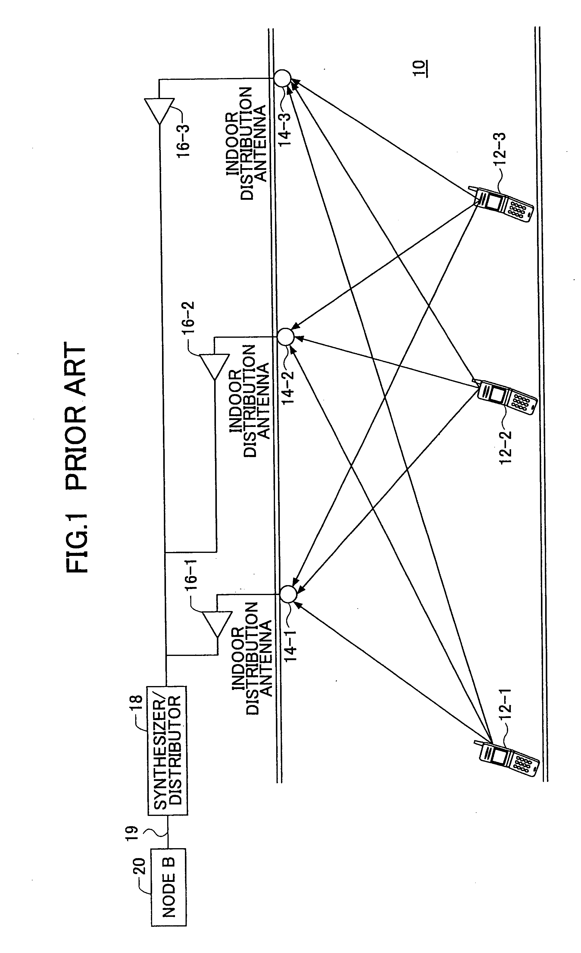
[0070]FIG. 9 is a schematic block diagram of a signal transmission system according to an embodiment of the present invention. The signal transmission system includes the synthesizer / distributor 88 shown in FIG. 8, plural signal processing parts 94-1˜N, and plural antennas 84-1˜N shown in FIG. 8, wherein N is a natural number. The synthesizer / distributor 88 includes a distributor 882 for DOWN LINK signals and a synthesizer 884 for UP LINK signals. Since each of the signal processing parts 94-1˜N has the same configuration and operates similarly, a first signal processing part 94-1 is described as an example. The signal processing part 94-1 includes a transmission line 942 (such as coaxial cable line, optical fiber line, radio transmission line and the like) for DOWN LINK signals, an amplifier 944, a band-pass filter 946, a circulator 948, a band-pass filter 950, an automatic power amplifier 952, a transmission line 954 (such as coaxial cable line, optical fiber line, radio transmiss...

second embodiment

[0087]FIG. 11 is a schematic block diagram of a signal transmission system according to an embodiment of the present invention. In FIG. 11, the same reference numerals of FIG. 9 are used to identify corresponding features. The signal processing part 94-1 in this embodiment includes components that have been described, in addition to those, it includes a band-pass filter 970, a power detector 972, a differential amplifier 974 and a control signal generation part 976.

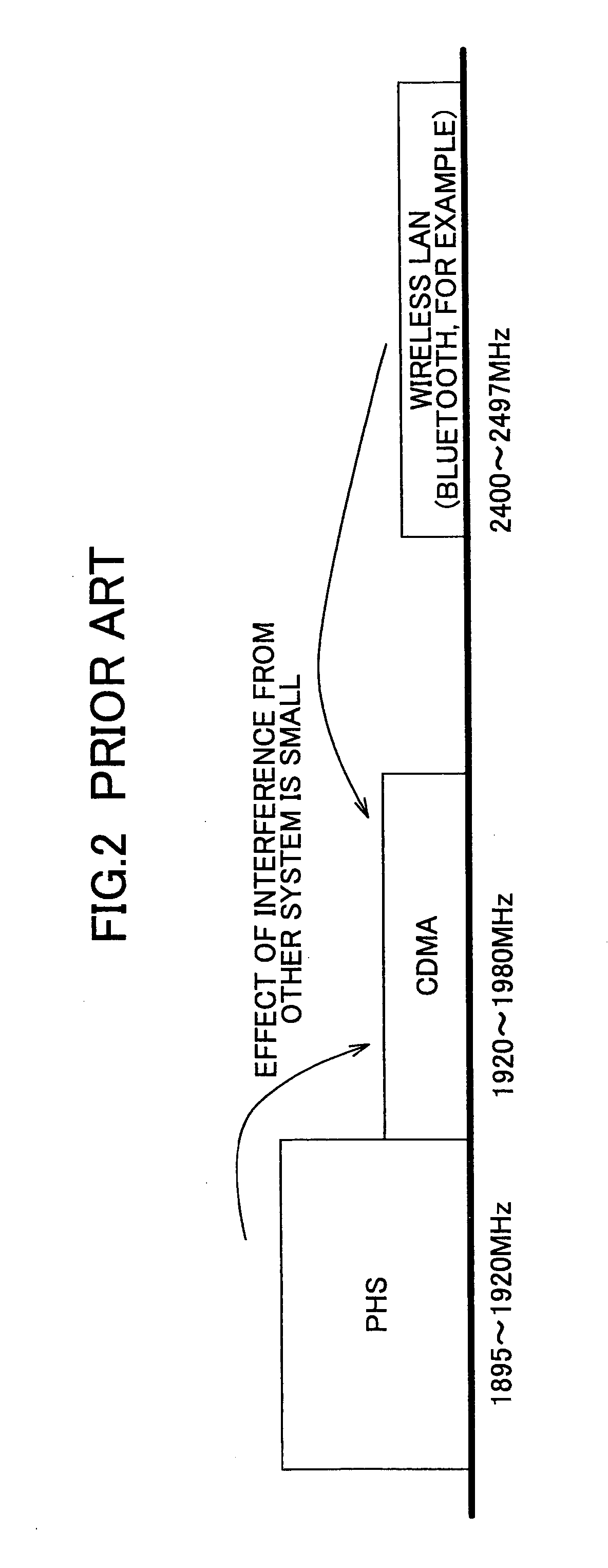
[0088] The band-pass filter 970 removes unnecessary frequency components from the UP LINK signal based on the band (2400˜2497 MHz, for example) used in the radio communication system of the wireless LAN scheme.

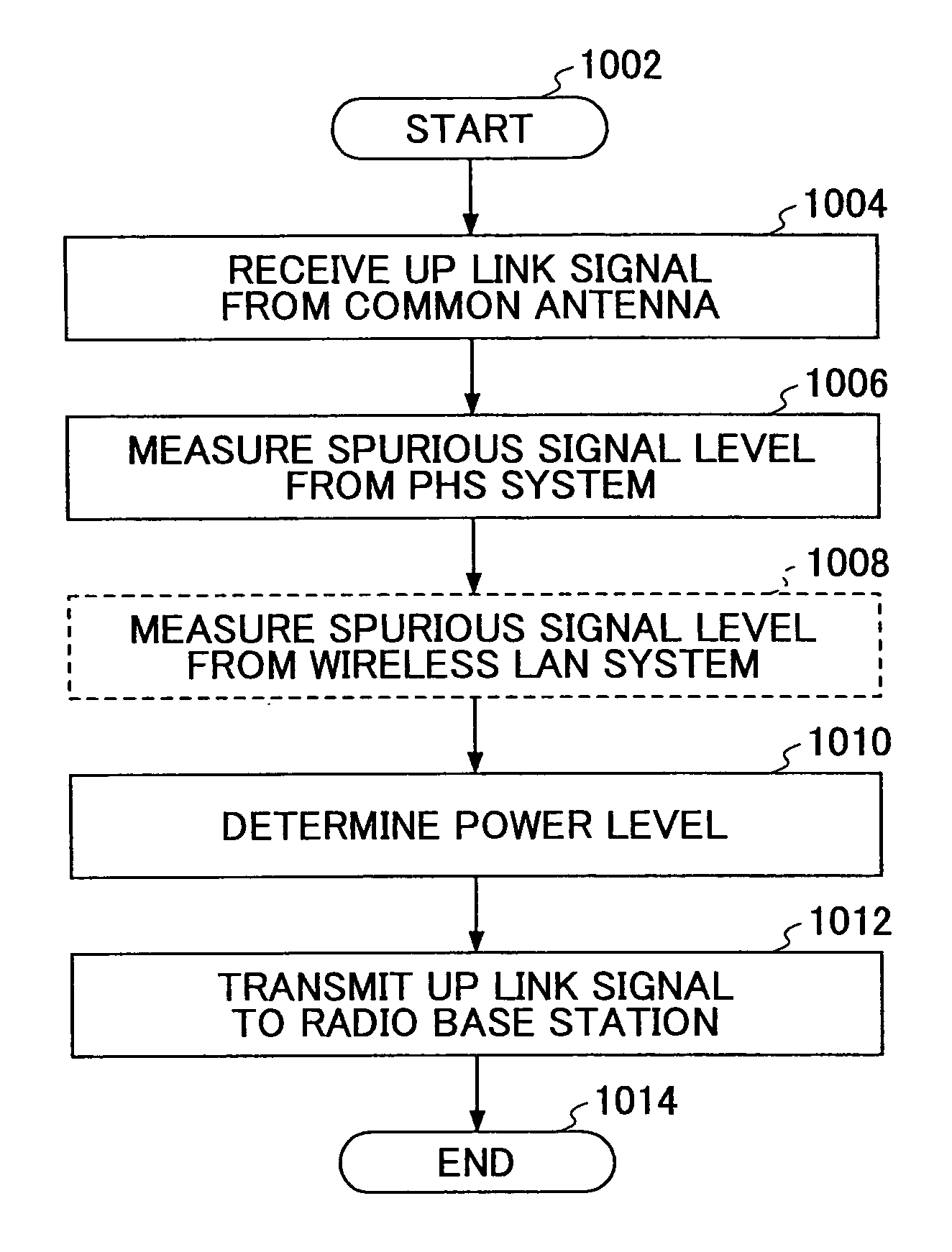
[0089] The power detector 972 detects that a signal component from the radio communication system of the wireless LAN scheme is included in the UP LINK signal, in other words, detects that a spurious signal is included in the UP LINK signal.

[0090] The differential amplifier 974 functions as a comparator for compa...

third embodiment

[0101]FIGS. 12 and 13 are functional block diagrams showing the signal transmission system of FIG. 11 in more detail. In FIG. 12, a DOWN LINK signal transmitted from a radio base station (node B) 1202 of the radio communication system of the W-CDMA scheme is supplied, via the circulator 1204, to a band-pass filter 1206 that passes a band for W-CDMA, and the signal is supplied to the synthesizer 1208. A DOWN LINK signal transmitted from a radio base station 1210 of PHS is supplied to the synthesizer 1208 viv a band-pass filter 1212 for PHS and a circulator 1214. A DOWN LINK signal from an access point (WiFi apparatus, for example) for wireless LAN is supplied to the synthesizer 1208 via a band-pass filter 1218 for wireless LAN and the circulator 1220. DOWN LINK signals of each radio communication system are synthesized by the synthesizer 1208, and are distributed to plural DOWN LINK transmission lines by the distributor 1222. Each of the transmission lines corresponds to a cell, and ...


PUM


Abstract

A signal transmission system for transmitting an UP LINK signal received by an antenna shared by at least a first radio communication system and a second radio communication system to at least a radio base station of the first radio communication system is provided. In the signal transmission system, the first radio communication system is affected by a spurious signal of a radio communication system other than the first radio communication system, and the signal transmission system includes: a determination part for determining whether a signal level of a signal, included in the UP LINK signal, from at least the second radio communication system exceeds a permissible level; and a level adjustment part for adjusting a power level of the UP LINK signal so as to output an adjusted signal according to the determination result, and sending the adjusted signal to the radio base station.

Description

BACKGROUND OF THE INVENTION [0001] 1. Field of the Invention [0002] The present invention generally relates to a signal transmission system and a signal transmission method. More particularly, the present invention relates to a signal transmission system and a signal transmission method used in a space in which plural radio systems exist concurrently. [0003] 2. Description of the Related Art [0004] Since radio communication technologies have progressed in recent years, various radio communication systems have been proposed, and standardization and commercialization of the various radio communication systems are being carried out. Therefore, there are some cases where plural radio communication systems concurrently exist in the same region. [0005]FIG. 1 is a schematic diagram showing a part of a space in which such plural radio communication systems exist. FIG. 1 shows plural mobile terminals 12-1, 2 and 3, plural antennas 14-1, 2 and 3, plural amplifiers 16-1, 2 and 3, a synthesizer...

Claims


Application Information

Patent Timeline
Patent Type & Authority Applications(United States)
IPC IPC(8): H04Q7/20H04B7/00H04W52/14H04W52/24
CPCH04W52/146H04W52/24
Inventor UTAKOUJI, AKIRAKAWASHIMA, SHINICHIONO, MITSUHIROTSUJI, KAZUTOMOOBA, TOSHINAO
Owner FUJITSU LTD
Why Eureka
Try Eureka