Jet engine inlet-fan system and design method

a jet engine and fan system technology, applied in the direction of machines/engines, supersonic fluid pumps, stators, etc., can solve problems such as performance penalties and implementation challenges, and achieve the effects of improving efficiency, reducing maintenance costs, and improving efficiency

Inactive Publication Date: 2006-08-17
MASSACHUSETTS INST OF TECH
View PDF8 Cites 76 Cited by
  • Summary
  • Abstract
  • Description
  • Claims
  • Application Information

AI Technical Summary

Benefits of technology

[0006] In a typical embodiment the blades of the rotating blade row are configured to produce a series of shock waves to decelerate the flow. In another embodiment, the fan further includes boundary layer suction as a means for boundary layer separation and shock position control on the blade surface and inner-outer annulus to enhance performance.
[0007] In another aspect, the invention is an integrated inlet / fan engine system for a supersonic aircraft. The system includes an inlet having a length selected to decelerate the flow from flight freestream supersonic velocity down to a velocity in the range of about Mach 1.2 to about Mach 1.3. A fan having a rotating blade row forming a fan face receives the decelerated absolute frame supersonic flow and decelerates the flow to a lower velocity exit flow while adding work to increase stagnation pressure of the flow.
[0008] The inventive inlet-fan system disclosed herein provides a shorter, lighter, and more efficient overall propulsion system for supersonic aircraft. The design disclosed herein provides for higher propulsion system efficiency that results in a reduction in fuel burn and longer aircraft range. The systems and methods described herein provide an engine with higher propulsion system mass flow having greater thrust for the same, or similar, size engine or smaller engines to meet a desirable or required aircraft thrust specification.
[0009] Weight and efficiency are competing propulsion system parameters having an impact on the overall goal of achieving environmentally-friendly supersonic flight over land and sustained long range cruise. The systems and methods disclosed herein reduce propulsion system length and weight, increase attendant payload, decrease fuel burn / consumption, and reduce sonic boom noise.
[0010] Bleed flow from the primary inlet flow stream is relied upon in conventional inlets to maintain stable operation and lower pressure losses. In contrast to these conventional inlets, the systems and methods described herein reduce or eliminate inlet bleed flows thereby increasing thrust and lowering drag and fuel burn.

Problems solved by technology

It is important to note that this STF fan design has absolute frame supersonic inlet and exit flow and in fact accelerates the flow to a higher Mach number resulting in performance penalties and implementation challenges.
Although the length of the inlet 10 upstream of the fan 14 of the engine in FIG. 2 is reduced, this reduced length is merely traded for a much more complex problem of designing an efficient, light diffuser after the flow leaves the fan.

Method used


Image

  • Jet engine inlet-fan system and design method
  • Jet engine inlet-fan system and design method
  • Jet engine inlet-fan system and design method

Examples


Embodiment Construction

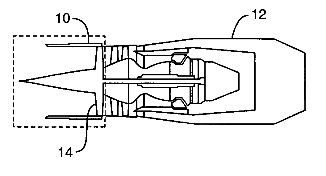
[0019] With reference now to FIG. 3 an engine 12 according to the invention includes a relatively short inlet (about half the length of a conventional supersonic inlet) section 10 and a fan 14 designed by the methods discussed below. The engine 12 is designed for use on supersonic aircraft having speeds typically on the order of Mach 2 or greater / lesser. Freestream air at Mach 2 or greater enters the inlet 10 and is decelerated to a Mach number ranging from approximately 1.2 -1.3 at the entry face of the fan 14. In this embodiment, the fan 14 decelerates the flow from the absolute frame supersonic velocity at its face to a subsonic velocity such as about Mach 0.5 at its exit. Not only does the fan 14 decelerate the flow from supersonic to subsonic conditions, the fan 14 also adds work to increase the stagnation pressure of the flow to a selected value. The subsonic flow leaves the fan 14 and enters the core engine as is well understood in the art.

[0020] The design procedure for an ...


PUM


Abstract

A supersonic aircraft engine axial fan that includes a rotating blade row having blades that receive a supersonic entry flow in the absolute frame and decelerate the flow to a lower supersonic or subsonic velocity exit flow while adding work to the flow to increase stagnation pressure. It is preferred that the lower velocity be subsonic. When the fan is combined with a suitably designed inlet, the propulsion system is compact and lighter in weight than conventional engines for supersonic aircraft.

Description

BACKGROUND OF THE INVENTION [0001] This invention relates to an engine for a supersonic aircraft and more particularly to an inlet and fan combination resulting in a significantly shorter, lighter and more efficient overall propulsion system for supersonic aircraft. A design method is also disclosed. [0002] Air entering an engine of a supersonic aircraft must be slowed down from a supersonic speed to a subsonic speed in order for the engine to perform properly. A typical engine for use with a supersonic aircraft is shown in FIG. 1. A rather long inlet section 10 (typically exceeding the length of the engine itself) of a prior art engine 12 acts as an interface between external freestream air and the engine. The deceleration is achieved by varying the flow area and through a series of shock waves that develop in the inlet section 10. In this conventional inlet more than half the length (and weight) is typically required to decelerate the flow to subsonic conditions suitable for engin...

Claims


Application Information

Patent Timeline
Patent Type & Authority Applications(United States)
IPC IPC(8): F02K3/04
CPCF02K3/04F02K3/06F05D2240/302Y02T50/671Y02T50/673F05D2220/80Y10S415/914Y02T50/60
Inventor MERCHANT, ALI
Owner MASSACHUSETTS INST OF TECH
Why Eureka
Try Eureka