Electric motor driven energy storage device for impacting

Inactive Publication Date: 2006-08-17
PEDICINI CHRIS +1
View PDF19 Cites 137 Cited by
  • Summary
  • Abstract
  • Description
  • Claims
  • Application Information

AI Technical Summary

Benefits of technology

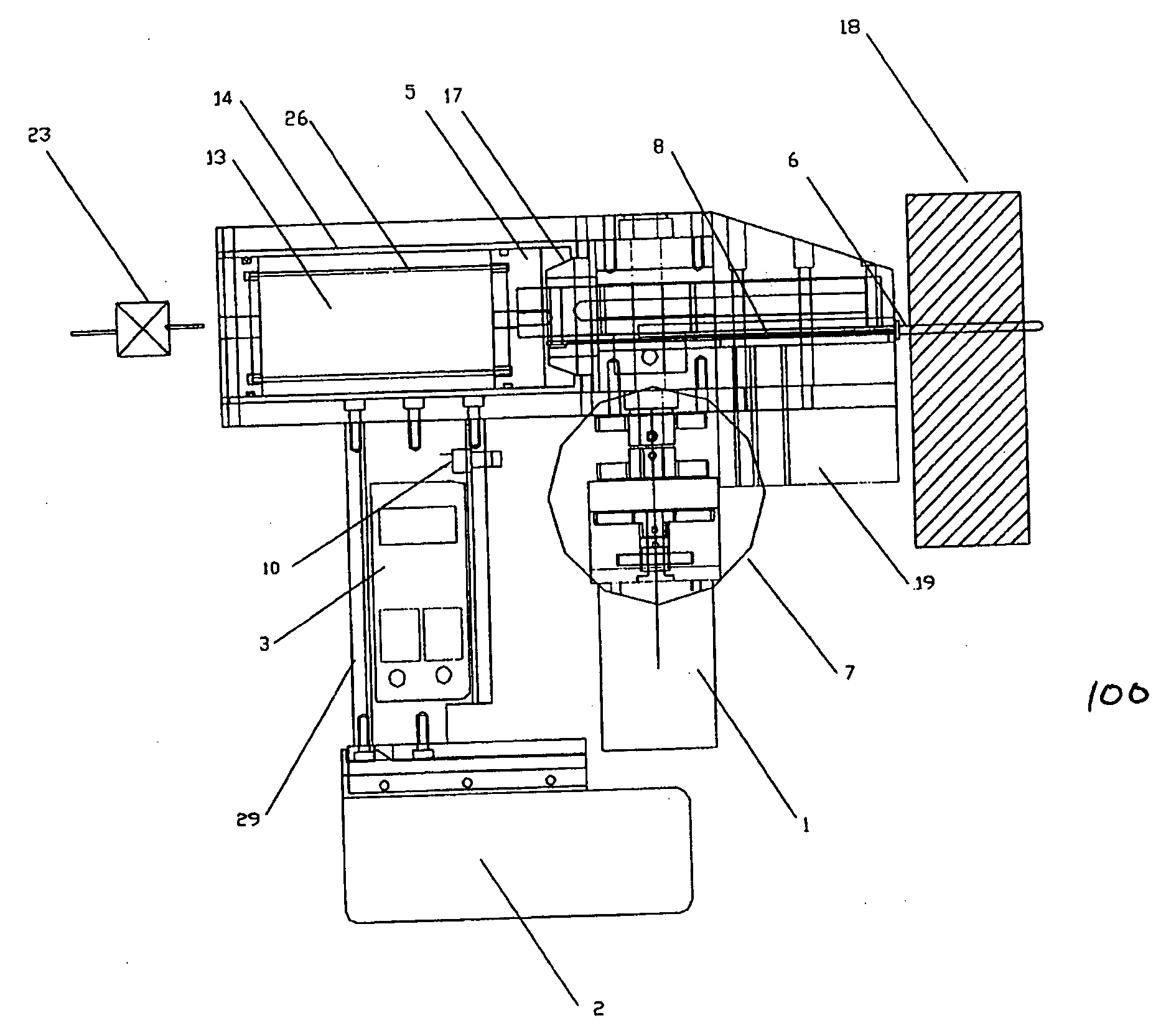
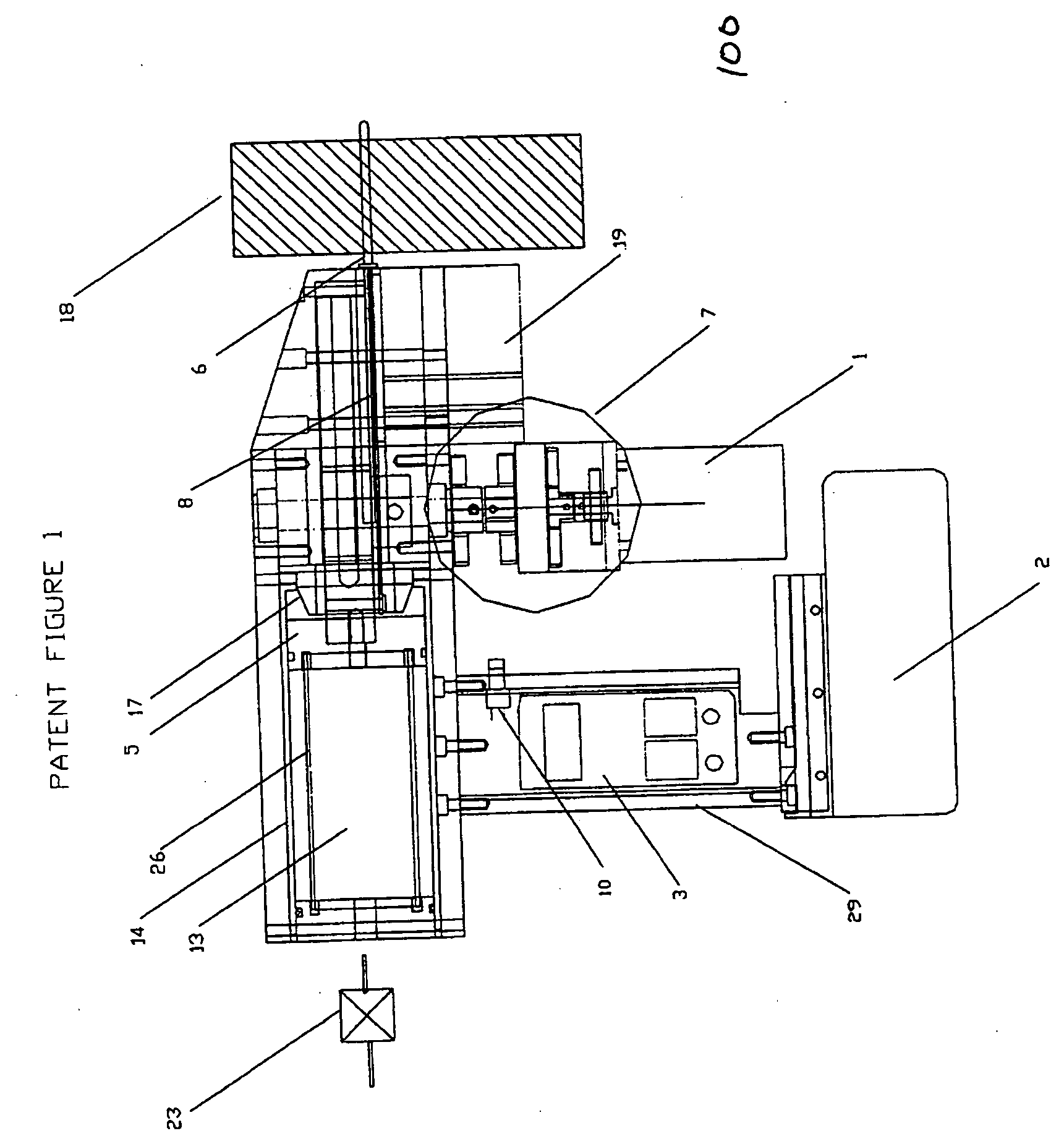
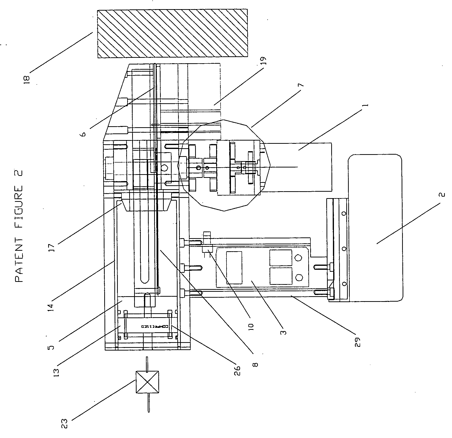
[0020] In accordance with the present invention, a fastening tool is described which derives its power from a low impedance electrical source, preferably rechargeable batteries, and uses a motor to transfer energy thru a linear motion converter into a piston which compresses air and stores the energy in the form of an air spring. The linear motion converter releases at a predetermined point thus allowing the compressed air to expand behind the piston and drive an anvil which pushes the fastener into the substrate. Upon receipt of an actuation signal from an electrical switch, a circuit connects a motor to the electrical power source. The motor is coupled to the linear motion converter preferably through a speed reduction mechanism. The linear motion converter changes the rotational motion of the motor into linear translating movement of the piston inside a cylinder. After the motor is connected to the power source, the gears and motor begin to spin which begins to transfer energy into the air spring formed by the piston and a closed end of a cylinder. When sufficient energy has been transferred to the air spring which is generally governed by the decoupling point of the linear motion converter to the drive train, the air spring freely moves the piston and fastener driving anvil through an output stroke. The preferred linear motion converter is a rack and pinion. In one design, some of the teeth of the pinion are removed which allows the rack, piston and anvil assembly to disengage from the drive when the rack is presented with the missing pinion teeth. At this disengagement point, the piston, rack and anvil assembly (fastener driving output assembly) is freely driven by the highly compressed air and rapidly drives the f

Problems solved by technology

A disadvantage is that it does however require that the user purchase an air compressor and associated air-lines in order to use this system.
Typical within this design is the need for a fairly complicated assembly.
One of the drawbacks of these types of mechanisms is that the number of ampere-turns in the solenoid governs the force provided by a solenoid.
These requirements are counterproductive because the resistance of the coil increases in direct proportion to the length of the wire in the solenoid windings.
This type of design suffers from a second drawback in that the force in a solenoid varies in relation to the distance of the solenoid core from the center of the windings.
This limits most solenoid driven mechanisms to short stroke small load applications such as paper staplers or small brad tackers.
There are several disadvantages in this design that include increased operator fatigue since the actuation technique is a series of blows rather than a continuous drive motion.
A further disadvantage is that this technique requires the use of an energy absorbing mechanism once the nail is seated.
Additionally, the multiple impact designs normally require a very heavy mechanism to insure that the driver does not move during the driving operation.
Several drawbacks exist to this design.
These include the need for a complex system of compressing and controlling the spring, and in order to store sufficient energy, the spring must be very heavy and bulky.
Additionally, the spring suffers from fatigue giving the tool a very short life.
Finally, metal springs must move a significant amount of mass in order to decompress, and the result is that the low speed nail drivers result in a high reactionary force on the user.
The major drawback to this design is the problem of coupling the flywheel to the driving anvil.
This prior art teaches the use of a friction clutching mechanism that is both complicated, heavy and subject to wear.
This design also suffers from difficulty in controlling the energy left over after the nail is driven.
Operator fatigue is also a concern as significant precession forces are present with flywheels that rotate in a continuous manner.
This design is limited by the large precession forces incurred because of the continuously rotating flywheel and the complicated and unreliable nature of the toggle link mechanism.
This patent overcomes some of the problems associated with the mechanical spring driven

Method used


Image

  • Electric motor driven energy storage device for impacting
  • Electric motor driven energy storage device for impacting
  • Electric motor driven energy storage device for impacting

Examples


Example

REFERENCE NUMBERS IN DRAWINGS

[0039]1 Motor [0040]2 Power Source [0041]3 Control Circuit [0042]4 Rack [0043]5 Piston [0044]6 Fastener [0045]7 Gear Reduction / Drive Train [0046]8 Anvil [0047]9 Linear Motion Converter [0048]10 Start Switch [0049]11 Drive Train Sensor [0050]12 Piston Position Sensor [0051]13 Air Chamber [0052]14 Cylinder [0053]15 Bolt Link [0054]16 Pinion Cutaway Teeth [0055]17 Bumper [0056]18 Substrate [0057]19 Fastener Feeder [0058]20 Positioning Spring [0059]21 Thermister [0060]22 Unused [0061]23 Release Valve [0062]24 Not Used [0063]25 Drive Train [0064]26 Piston Return Spring [0065]27 Not Used [0066]28 Sear Pin / Lever [0067]29 Grip [0068]30 Support Bearing [0069]31 Rack Pinion [0070]32 Trigger [0071]33 Unused [0072]34 Clutch [0073]62 Microprocessor [0074]64 Power switching elements [0075]100 Apparatus

DETAILED DESCRIPTION OF THE INVENTION

[0076] The operation of the invention in driving a fastener into a substrate has significant improvements over that which is avai...


PUM

PropertyMeasurementUnit
Poweraaaaaaaaaa
Energyaaaaaaaaaa
Electric impedanceaaaaaaaaaa

Abstract

A portable electric fastening tool operating from a power supply. The motor moves a piston which compresses air against a sealed chamber. The piston is coupled to a fastener impacting anvil and is released after sufficient energy is stored in the air chamber. The air energetically expands pushing the piston and fastener driving anvil into the substrate. The actuation is governed by a control circuit and initiated from a trigger switch. The stored energy delivered from the motor is coupled to the output anvil and drives the nail. At least one position of the output anvil is sensed and once the nail is driven, the power can be disconnected from the motor. This method uses a rack and a pinion to drive the piston thus reducing wear and increasing efficiency of the device. Elastic bumpers are used at the end of the stroke to limit stresses during the impact. The electrical control circuit and sensors allow precise control and improve safety. An intermediate clutch is used to increase reliability and performance. The power supply is preferably a rechargeable low impedance battery pack.

Description

PRIORITY [0001] The present invention claims priority under 35 USC section 119 based on the patent application 60 / 653,571 filed on Feb. 16, 2005.FIELD OF THE INVENTION [0002] This invention relates to fastening mechanisms, specifically to such nail or staple fastening mechanisms that require operation as a hand tool. BACKGROUND OF INVENTION [0003] An electromechanical fastener-driving tool weighs generally less than 15 pounds and is completely suitable for an entirely portable operation. [0004] Contractors and homeowners commonly use power-assisted means of driving fasteners into wood. These power assisted means of driving fasteners can be either in the form of finishing nail systems used in baseboards or crown molding in house and household projects, or in the form of common nail systems that are used to make walls or hang sheathing onto same. These systems can be portable (not connected or tethered to an air compressor or wall outlet) or non-portable. [0005] The most common fasten...

Claims


Application Information

Patent Timeline
IPC IPC(8): B25C1/04
CPCB25C1/06
Inventor PEDICINI, CHRISWITZIGREUTER, JOHN
Owner PEDICINI CHRIS
Why Eureka
Try Eureka