Switching power supply apparatus and electronic device using the same

a technology of electrical equipment and electronic devices, applied in the direction of electric variable regulation, process and machine control, instruments, etc., can solve the problems of increasing the overall size of the transformer, increasing the loss of switching elements, and the decrease of the turn ratio n, so as to reduce the noise transmission through the windings, stable output characteristics, and efficient utilization of regions

Inactive Publication Date: 2006-08-17
PANASONIC CORP
View PDF5 Cites 10 Cited by
  • Summary
  • Abstract
  • Description
  • Claims
  • Application Information

AI Technical Summary

Benefits of technology

[0025] In the switching power supply unit of the present invention, the windings as the transformer are formed of copper foil patterns stacked on a multilayer printed board. This structure can reduce the noise transmission through the windings, thereby providing stable output characteristics.
[0026] In the switching power supply unit of the present invention, the copper foil patterns are formed one turn per layer of the multilayer printed board, and the copper foil patterns on the multilayer printed board are interconnected by a connection unit. This structure enables the efficient utilization of the regions on which to form the windings so as to miniaturize the switching power supply unit.
[0027] In the switching power supply unit of the present invention, the connection unit is formed outside the copper foil patterns. This structure enables the efficient utilization of the regions on which to form the windings so as to miniaturize the switching power supply unit.
[0028] In the switching power supply unit of the present invention, the switching power supplies are half-bridge converters. This structure can provide lower output voltage, thereby miniaturizing the transformer.
[0029] In the switching power supply unit of the present invention, the switching elements of the plurality of switching power supplies are switched on and off at regular intervals. This structure can achieve ripple cancellation, thereby providing stable output voltage.
[0030] The electronic device of the present invention is designed to supply electric power to a semiconductor device such as a semiconductor component by using the aforementioned switching power supply unit. The switching power supply unit thus miniaturized can downsize the whole electronic device and can also supply stable output voltage, so that the electronic device can have stable characteristics.

Problems solved by technology

However, an increased number of turns of windings in the transformer increases the volume necessary for the insulation between the windings, thereby increasing the overall size of the transformer.
Thus, a decrease in turns ratio N mainly increases the loss of the switching elements.
As a result, it is inevitable that the transformer itself grows in size.
This develops a lot of spaces where no current can flow so as to reduce the usability, thereby leaving the problem of the growth of the transformer in size.
This conventional structure has a problem in that when the windings of the transformer are made up of a multilayer board or a stack of planar conductors, a small turns ratio causes the loss of the switching elements, and increasing the turns ratio to reduce the loss increases the transformer in size.
The structure has another problem in that the use of the multilayer board or the stack of planer conductors increases the stray capacity between the coils, and the increased stray capacity allows a larger amount of noise to be transmitted by the switching voltage waveform generated by the on-off of the first and second switching elements, thereby deteriorating the stability.

Method used


Image

  • Switching power supply apparatus and electronic device using the same
  • Switching power supply apparatus and electronic device using the same
  • Switching power supply apparatus and electronic device using the same

Examples


first exemplary embodiment

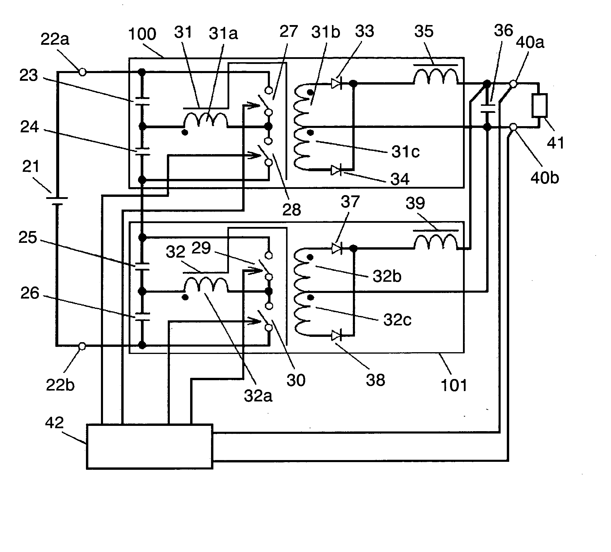
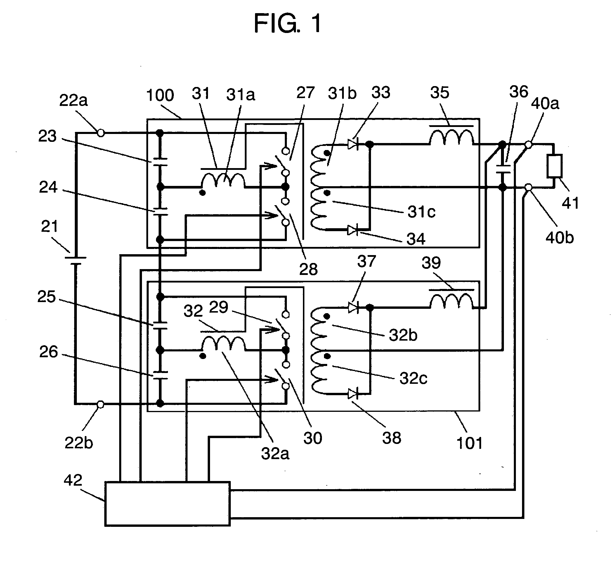
[0096]FIG. 1 shows a circuit block diagram of a switching power supply unit according to a first embodiment of the present invention.

[0097] In FIG. 1, input DC voltage 21 is placed between input terminals 22a and 22b. First capacitor 23, second capacitor 24, third capacitor 25 and fourth capacitor 26 are connected in series between input terminals 22a and 22b. First switching element 27 and second switching element 28 are connected in series, and are connected with the series circuit of first and second capacitors 23 and 24. The series circuit of third switching element 29 and fourth switching element 30 is connected to both ends of the series circuit of third and fourth capacitors 25 and 26.

[0098] First transformer 31 includes primary winding 31a, first secondary winding 31b and second secondary winding 31c. First and second secondary windings 31b and 31c are connected in series. Second transformer 32 includes primary winding 32a, first secondary winding 32b and second secondary ...

second exemplary embodiment

[0133]FIG. 4 is a circuit block diagram showing the structure of a switching power supply unit of a second embodiment of the present invention. The second embodiment differs from the first embodiment shown in FIG. 1 in that three half-bridge converters instead of two are used. Each half-bridge converter basically operates in the same manner as described in the first embodiment, so that the description will not be repeated. In FIG. 4, the same components as those shown in FIG. 1 are referred to with the same reference marks.

[0134] In FIG. 4, input DC voltage 21 is placed between input terminals 22a and 22b. First half-bridge converter 300 has first transformer 47. Second half-bridge converter 301 has second transformer 48. Third half-bridge converter 302 has third transformer 49. The output currents of the three half-bridge converters are added up and smoothed to absorb ripple currents.

[0135] Output terminals 40a and 40b are commonly connected to output the outputs of half-bridge c...


PUM

PropertyMeasurementUnit
voltageaaaaaaaaaa
voltageaaaaaaaaaa
output voltageaaaaaaaaaa

Abstract

Provided is a switching power supply unit which uses a multilayer board or a stack of planar conductors as the windings of transformers so as to reduce the volume of the transformers and to have high efficiency, small size and small noise. The switching power supply unit is formed by connecting a plurality of capacitors (23), (24), (25) and (26) connected in series with each other to input terminals (22a) and (22b) of a plurality of switching power supplies having switching elements (27), (28), (29) and (30), transformers (31) and (32), and rectifiers (33), (34), (37) and (38). The switching power supply unit inputs the voltages of capacitors (23)-(26), and outputs the respective voltages developed by the plurality of switching power supplies together to common output terminals (40a) and (40b). The transformers (31) and (32) are each composed of windings made up of a stack of planar conductor coils. This structure can reduce noise transmission through the windings, thereby providing stable output characteristics.

Description

TECHNICAL FIELD [0001] The present invention relates to a switching power supply unit for supplying DC stabilized voltage to electronic devices for industrial and consumer use, and also relates to an electronic device using the switching power supply unit. BACKGROUND ART [0002] As electronic devices are getting less expensive, more compact, more sophisticated and more energy-efficient, switching power supply units are strongly expected to be smaller, highly efficient and to have stable output characteristics. In recent years, semiconductor components, particularly microprocessors, have been having lower voltage and larger current. Along with this trend, in order to secure the supply of more stable voltage and larger current, there is now a transition from the concentrated power-supply system to the distributed power-supply system in which power is supplied in the vicinity of semiconductor devices such as semiconductor components. In the distributed power-supply system, it is necessa...

Claims


Application Information

Patent Timeline
Patent Type & Authority Applications(United States)
IPC IPC(8): G05F1/12G05F1/46H01F17/00H01F27/28H01F30/00H02M3/28H02M3/335H02M3/337
CPCH01F27/2804H01F2017/002H02M3/285H02M3/3376H02M2001/0074H02M1/0074
Inventor YOSHIDA, KOJIMATSUO, MITSUHIROTAKESHIMA, YOSHIHIRO
Owner PANASONIC CORP
Why Eureka
Try Eureka