Apparatus and method for communication system

Inactive Publication Date: 2006-08-17
ORTRONICS INC
View PDF35 Cites 33 Cited by
  • Summary
  • Abstract
  • Description
  • Claims
  • Application Information

AI Technical Summary

Benefits of technology

[0029] In a further exemplary embodiment of the present disclosure, a double balance electrical noise reduction device facilitates insertion of DC power. The device may be advantageously used for high frequency transfer of data signals to interface connectors for unshielded twisted pair, i.e., UTP, media. The disclosed device generally utilizes a low reactance modular insert with two stage positive and negative compensation techniques to produce low noise characteristics. The device also allows for the insertion of DC power on signal lines without compromising system performance.
[0030] In an exemplary embodiment of the present disclosure, the disclosed UTP connector reduces connecting hardware cross-over talk (i.e., NEXT noise) and communicates with a high frequency DC power coupling device. The connector is advantageously designed so to have no substantial impact on (i.e., does not substantially lessen) the impedance characteristics of connected wire pairs below minimum Category 5e performance.
[0031] A

Problems solved by technology

The distortions and additional unwanted signals are typically inserted by the transmission system somewhere between transmission and reception.
The unwanted signals are referred to as noise, which can be a major limiting factor in the performance of a communication system, e.g., due to data errors, system malfunctions and/or loss of desired signal(s).
Generally spea

Method used


Image

  • Apparatus and method for communication system
  • Apparatus and method for communication system
  • Apparatus and method for communication system

Examples


Embodiment Construction

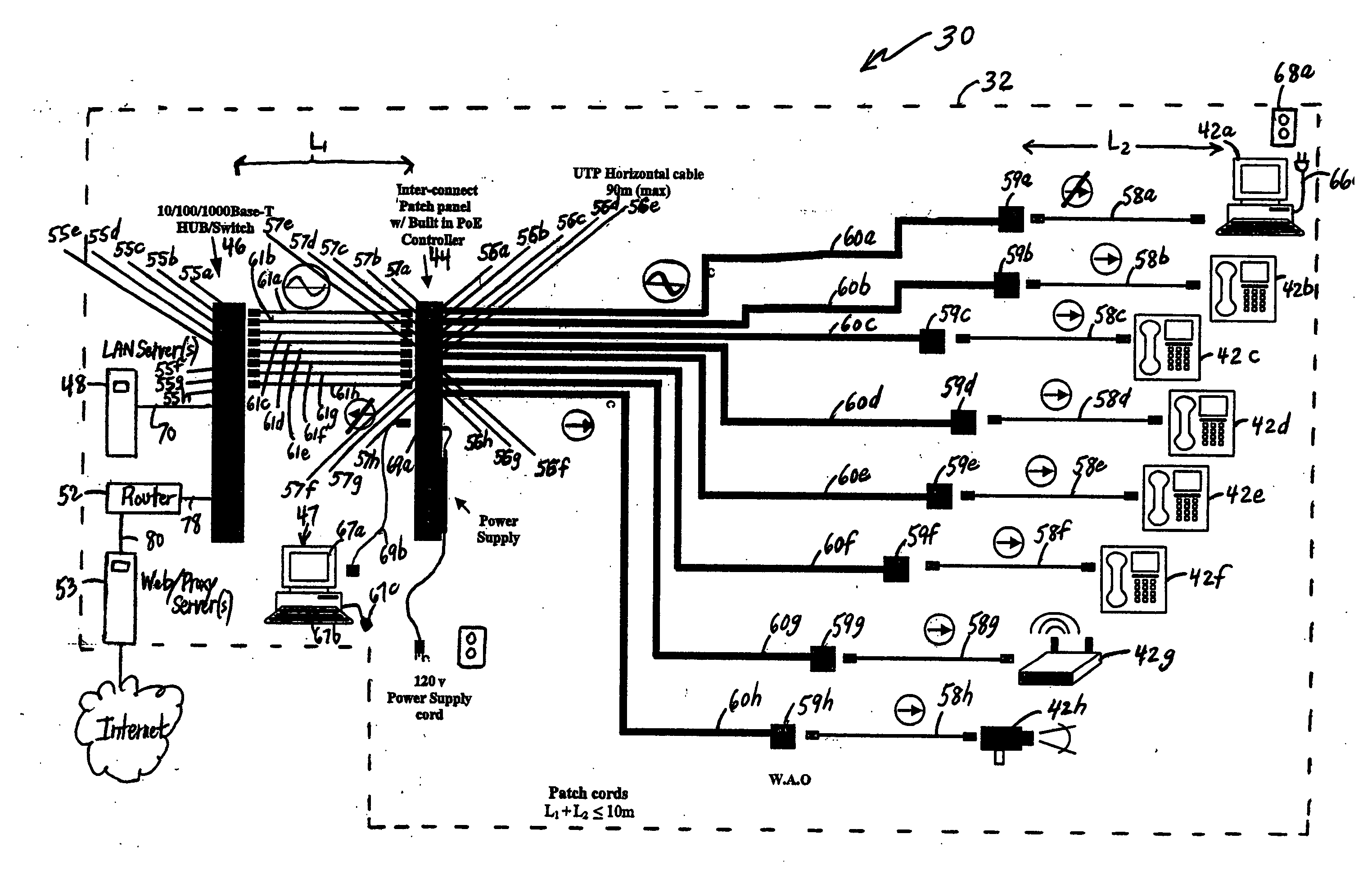
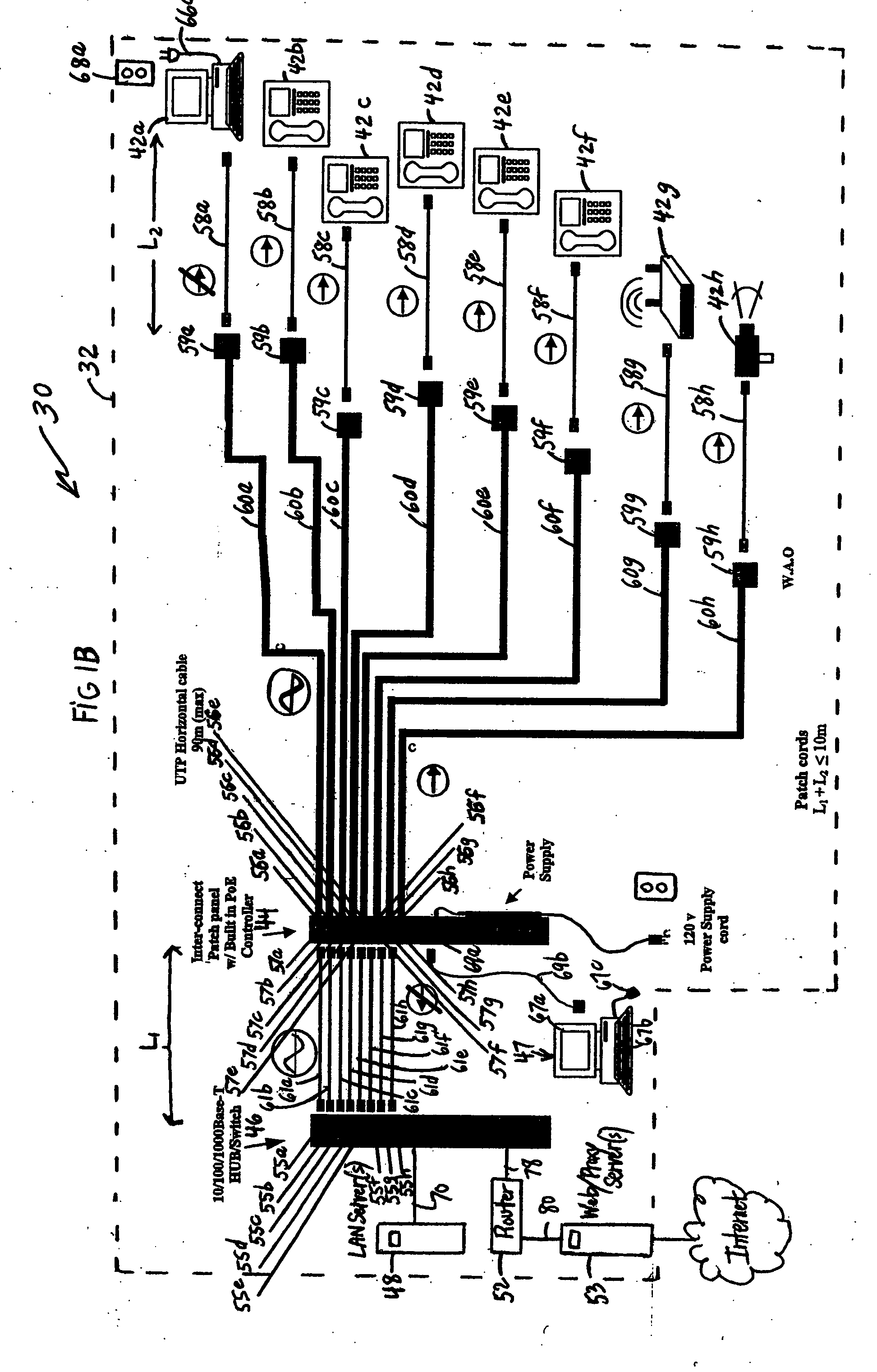
[0062] According to the present disclosure, advantageous patch panel and power distribution systems are provided. Exemplary embodiments of the present disclosure include advantageous components, assemblies and sub-assemblies that may be employed in power distribution applications, e.g., power over Ethernet applications, as described herein. The disclosed components, assemblies, sub-assemblies and systems are particularly advantageous for inserting or introducing power to data communication line(s) in an efficient and reliable manner. Advantageous structural and functional aspects of the disclosed components, assemblies, sub-assemblies and systems, and methods for use thereof, will be apparent to persons skilled in the art from the detailed description which follows, particularly when read in conjunction with the appended figures.

[0063]FIG. 1B is a block diagram representation of a communication system 30 in accordance with one embodiment of one aspect of the present disclosure. The...


PUM


Abstract

An apparatus/system for use in coupling power from a power supply to a device over a network transmission medium is provided. The coupling apparatus/system generally includes one or more common mode chokes that feature a first winding and a second winding, the first winding being electrically connected between the first terminal of the power supply and the first electrical conductor of the network transmission medium, and the second winding being coupled between the first terminal of the power supply and the first electrical conductor of the network transmission medium. The common mode choke generally includes at least one core for coupling the first and second windings of the one or more common mode chokes. An RJ45 to 110 IDC modular connector may be connected to a printed circuit board used to transfer high speed signals for telecommunication interface media connections. The printed circuit board is configured to help reduce near-end crosstalk (NEXT) without compromising impedance. DC power is coupled upon the signal line by utilizing a wideband high impedance common mode choke design.

Description

BACKGROUND [0001] 1. Technical Field [0002] The present disclosure relates to communication systems and methods and to advantageous devices, systems and / or components for use in association therewith. [0003] 2. Background Information [0004] A network, e.g., a local area network (LAN), typically includes a plurality of personal computers and / or other devices (e.g., processors, servers, IP telephones, cameras, and the like) that are interconnected via network transmission media (e.g., wires and / or cables) and / or other network devices (e.g., hubs, switches, patch panels and the like). Personal computers and other network devices have traditionally received power from wall mounted outlets that supply 120 VAC (voltage alternating current). However, it has been determined that the need to receive power from wall mounted outlets can be eliminated, or at least reduced, in certain instances. One such circumstance involves devices that are connected to networks. [0005] More particularly, devi...

Claims


Application Information

Patent Timeline
IPC IPC(8): H01Q9/04H04M9/08
CPCH04B3/32H04H20/84H05K1/0228H05K1/0239H05K2201/10189
Inventor AEKINS, ROBERT A.DUPUIS, JOSEPH E.
Owner ORTRONICS INC
Why Eureka
Try Eureka