Joined body and manufacturing method for the same

a joint body and manufacturing method technology, applied in the field of joint bodies, can solve the problems of deformation of ceramic members and deterioration of the quality of the surface of ceramic members, and achieve the effect of preventing deformation and deterioration of quality

Active Publication Date: 2006-08-17
NGK INSULATORS LTD
View PDF13 Cites 25 Cited by
  • Summary
  • Abstract
  • Description
  • Claims
  • Application Information

AI Technical Summary

Benefits of technology

[0010] According to the joined body and the method for manufacturing the same, which are as described above, the joining temperature can be set as low as lower than ...

Problems solved by technology

However, in each of the solid phase joining and the liquid phase joining, a joining temperature is as high as 1500° C. or higher, and accordingly, t...

Method used


Image

  • Joined body and manufacturing method for the same
  • Joined body and manufacturing method for the same
  • Joined body and manufacturing method for the same

Examples


example 1

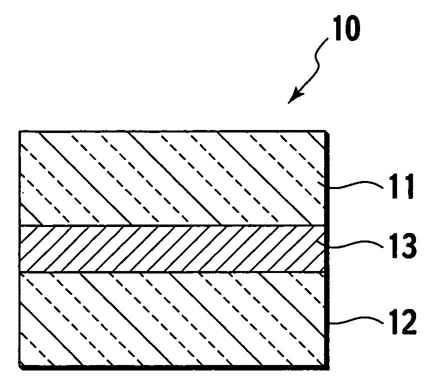
[0043] In this example, the joined body 10 shown in FIG. 1 was fabricated.

[0044] First, disk shaped sintered bodies with a diameter of 40 mm and a thickness of 20 mm were prepared as the first ceramic member 11 and the second ceramic member 12. In this example, aluminum nitride, silicon carbide, alumina, or silicon nitride was used. Moreover, as the joining material for forming the joining layer 13, an aluminum alloy (JIS BA4004) with a diameter of 40 mm and a thickness of 0.1 mm was prepared.

[0045] Next, the above-described joining material was inserted between the fist ceramic member 11 and the second ceramic member 12. The thermal compression was performed for the first ceramic member 11 and the second ceramic member 12 in a state where the joining material was interposed therebetween. Specifically, by using a hot pressing apparatus, the first ceramic member 11, the second ceramic member 12, and the joining material were raised in temperature up to 550° C. which was lower than ...

example 2

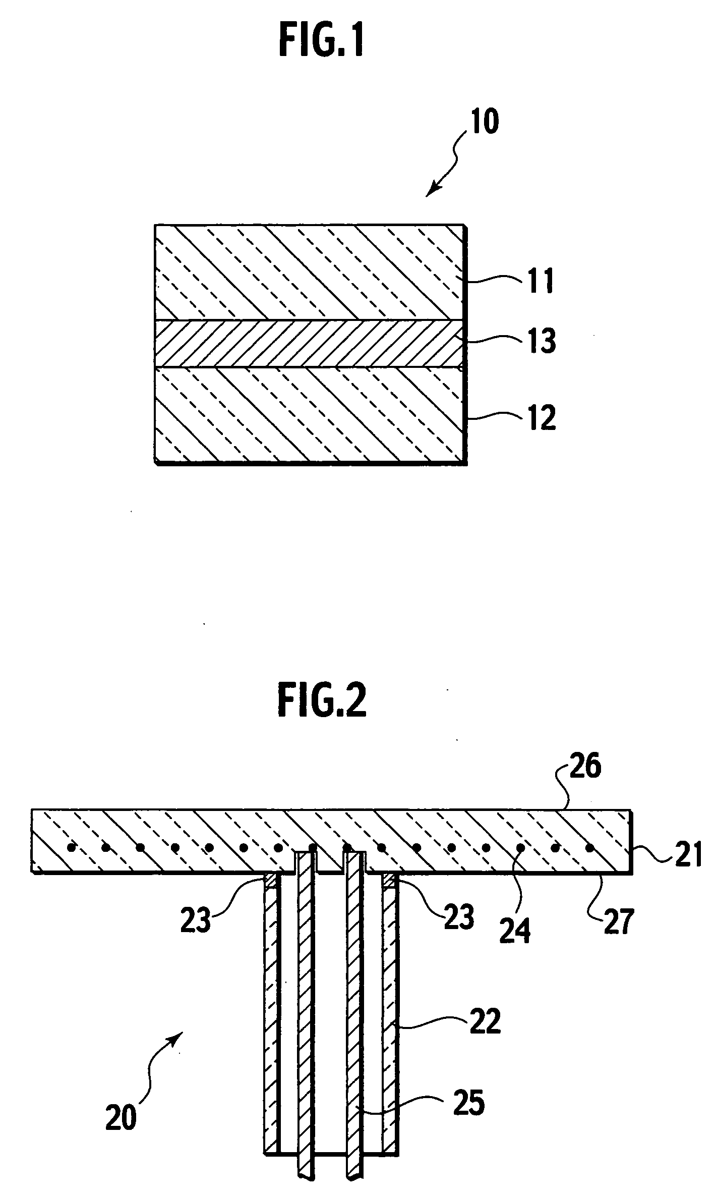
[0056] The ceramic heater 20 shown in FIG. 2 was fabricated. First, the base 21 was fabricated. 95 wt % aluminum nitride powder and 5 wt % yttria (Y2O3) powder as sintering aids were mixed together, and raw material powder was thus prepared. A plate-like molded body was fabricated by using the raw material powder. At this time, coil-like molybdenum was embedded as the resistance heating element 24 in the molded body, and an integrally molded body made of the aluminum nitride and the resistance heating element 24 was formed. The molded body was fired by a hot pressing method, and the plate-like aluminum nitride sintered body in which the resistance heating element 24 was embedded was fabricated. The aluminum nitride sintered body was subjected to contour processing, grinding processing for a joined surface thereof to the tubular member 22, drilling processing for inserting the feeder members 25, and the like, and the base 21 with a diameter of 300 mm and a thickness of 15 mm was thus...


PUM

PropertyMeasurementUnit
Temperatureaaaaaaaaaa
Fractionaaaaaaaaaa
Thicknessaaaaaaaaaa

Abstract

A joined body includes a first ceramic member, a second ceramic member, and a joining layer which contains soft metal, and joins the first ceramic member and the second ceramic member to each other by being thermally compressed at a joining temperature lower than a solidus of the soft metal.

Description

CROSS REFERENCE TO RELATED APPLICATIONS [0001] This application is based upon and claims the benefit of priority from prior U.S. Provisional Application No. 60 / 653,320, filed on Feb. 16, 2005; the entire contents of which are incorporated herein by reference.BACKGROUND OF THE INVENTION [0002] 1. Field of the Invention [0003] The present invention relates to a joined body in which ceramic members are joined together, and to a manufacturing method for the same. [0004] 2. Description of the Related Art [0005] Heretofore, as methods for manufacturing a joined body by joining plural ceramic members together, solid phase joining, liquid phase joining, and the like have been proposed. For example, there has been proposed a method, in which yttrium nitrate is coated on joined surfaces of aluminum nitride members, and the aluminum nitride members are subjected to the solid phase joining at 1800° C. (refer to Japanese Patent Laid-Open Publication No. H8-73280 (published in 1996)). Moreover, t...

Claims


Application Information

Patent Timeline
IPC IPC(8): B28B11/00
CPCC04B35/645C04B35/6455C04B37/006C04B2235/6581C04B2235/96C04B2235/9607Y10T428/131C04B2237/343C04B2237/365C04B2237/366C04B2237/368C04B2237/708H05B3/283C04B2237/121A61J1/16A61J1/1412
Inventor FUJII, TOMOYUKI
Owner NGK INSULATORS LTD
Why Eureka
Try Eureka