Porous structures useful as bipolar plates and methods for preparing same

a technology of porous structures and bipolar plates, applied in the field of porous structures, can solve the problems of ineffective delivery of reactants and persisting corrosion problems, and achieve excellent chemical, electrochemical and thermal stability

Inactive Publication Date: 2006-08-17
COMMISSARIAT A LENERGIE ATOMIQUE ET AUX ENERGIES ALTERNATIVES
View PDF9 Cites 21 Cited by
  • Summary
  • Abstract
  • Description
  • Claims
  • Application Information

AI Technical Summary

Benefits of technology

[0042] it allows the porosity of the various constituent parts of the porous region to be controlled;
[0043] it makes it possible, thanks to the materials used which are all based on carbon, to obtain a region exhibiting excellent chemical, electrochemical and thermal stability; and

Problems solved by technology

However, it has been found that this particular arrangement of means does not provide an exchange area large enough to result in an electrochemical conversion efficiency that is acceptable for an industrial application.
Even though the problem associated with electrical conduction can be partly solved by compressing the metal foam, it nevertheless turns out that corrosion problems persist, owing to the highly corrosive chemical nature of the environment of this type of fuel cell, even by using non-corrodible coatings, and especially because of the presence of many defects such as strand breaks within the metal foam.
they do not allow effective delivery of the reactants, owing to an insufficient area for exchange between the structure and the element to be supplied with fluid;
they generate, owing to the fact that they may consist of several parts possibly made of different materials, a contact resistance and corrosion problems.

Method used


Image

  • Porous structures useful as bipolar plates and methods for preparing same
  • Porous structures useful as bipolar plates and methods for preparing same

Examples


first embodiment

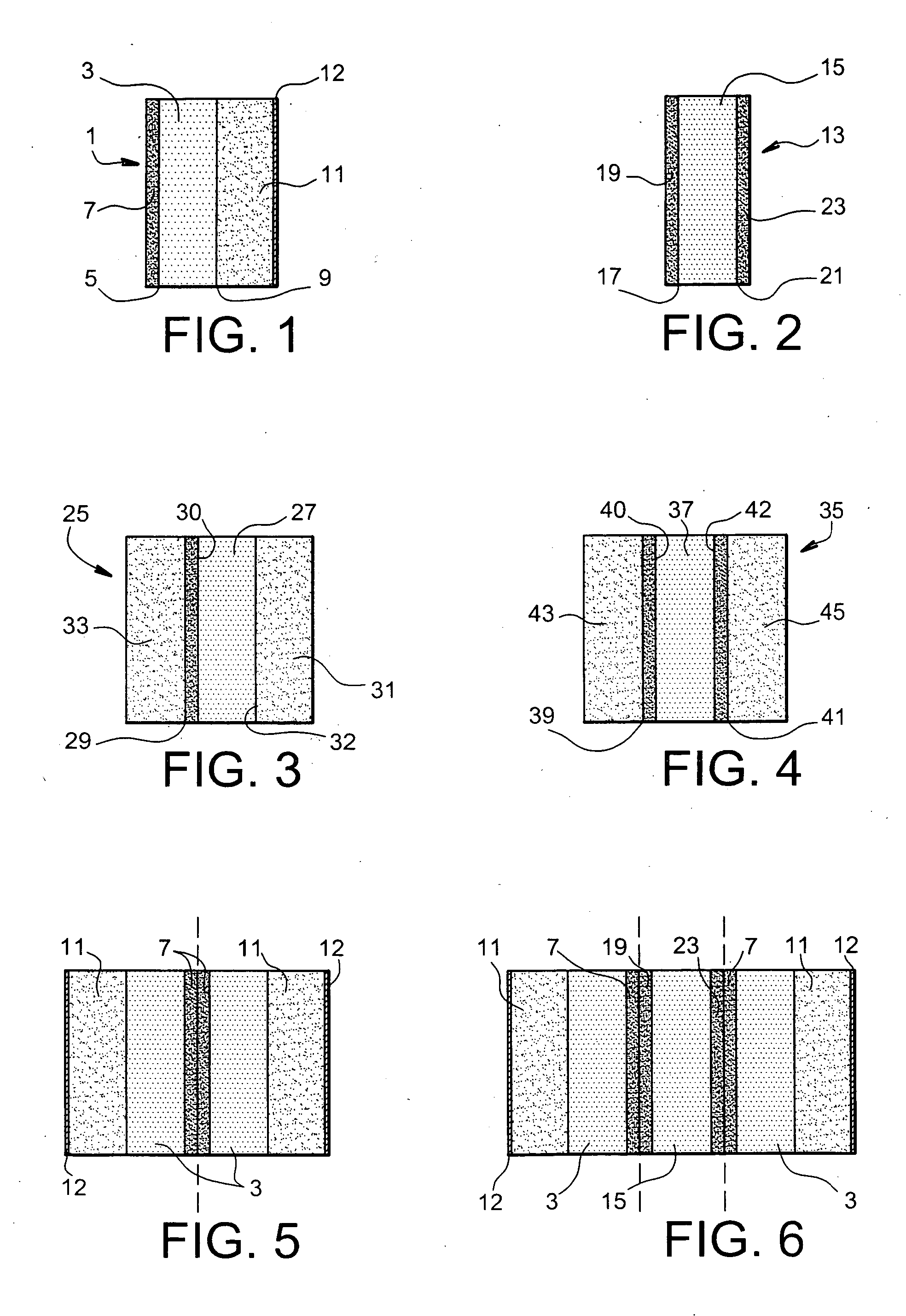
[0055] Thus, shown in particular in FIG. 1, the porous structure 1 comprises a porous carbon-fibre matrix 3 bounded on a first face 5 by an impermeable layer 7, exhibiting the abovementioned features, and on a second face 9 opposite the first face 5 by a porous layer 11 made of a carbon element chosen from carbon fibres and carbon nanotubes, said porous layer 11 being linked by carbon-carbon bonds to the porous matrix 3. It will be understood that the porous layer will have a predetermined porosity depending on the dedicated use to which this layer is put.

second embodiment

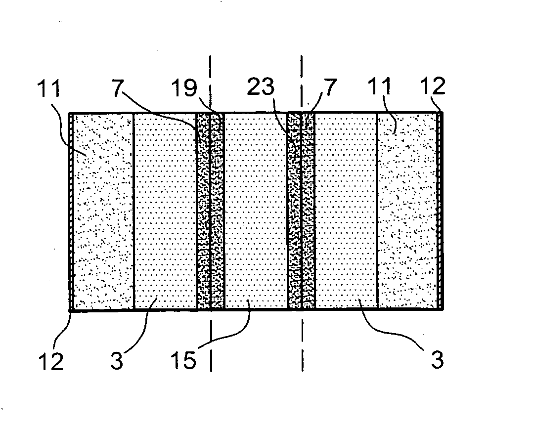
[0056] shown in FIG. 2, the porous structure 13 comprises a porous matrix 15 bounded on a first face 17 by an impermeable layer 19 and on a second face 21 opposite the first face by another impermeable layer 23, the said impermeable layers 19, 23 being as defined above.

[0057] The porous structures of the invention may also include a porous layer, made of a carbon element chosen from carbon fibres and carbon nanotubes, on the abovementioned impermeable layer or layers and / or on a face of the porous matrix, as shown in particular in FIGS. 3 and 4.

[0058] Thus, FIG. 3 shows a porous structure 25 comprising a porous matrix 27, bounded on a face 30 by an impermeable layer 29 and on the opposite face 32 by a porous layer 31 as shown in FIG. 1, and also another porous layer 33 on said impermeable layer 29.

[0059]FIG. 4 shows a porous structure 35 comprising a porous matrix 37 bounded on two opposed faces 40, 42 by two impermeable layers 39, 41 on either side of said porous matrix 37, to w...


PUM

PropertyMeasurementUnit
temperatureaaaaaaaaaa

Abstract

The invention relates to a porous structure, characterized in that it comprises a porous matrix (15) made of carbon fabric, said porous matrix being bounded on at least one of its faces (17, 21) by an impermeable layer (19, 23) made of an element chosen from carbon fibres, carbon nanotubes and glassy carbon, said impermeable layer being linked to the porous matrix via carbon-carbon bonds. The invention also relates to a process for manufacturing such porous structures. Application to the fields of fuel cells and heat exchangers.

Description

TECHNICAL FIELD [0001] The present invention relates to porous structures that can be used in particular as bipolar plates or as an electrode / bipolar plate assembly in fuel cell devices. [0002] The invention also relates to a process for manufacturing such porous structures. [0003] The general field of the invention may be defined as that of fuel cells, in particular fuel cells of the solid-state polymer electrolyte type. PRIOR ART [0004] A fuel cell is an assembly generally comprising a plurality of cell elements stacked on top of one another. In each cell element of the fuel cell, an electrochemical reaction is created between two reactants that are introduced continuously into the cell elements. The fuel normally used is hydrogen or methanol, depending on whether this is a cell operating with mixtures of the hydrogen / oxygen type (a cell of the PEMFC type) or a cell operating with mixtures of the methanol / oxygen type (a cell of the DMFC type), respectively. [0005] The fuel is brou...

Claims


Application Information

Patent Timeline
Patent Type & Authority Applications(United States)
IPC IPC(8): H01L21/20H01M8/02
CPCH01M8/0234H01M8/0245Y02E60/50Y02P70/50
Inventor MOSDALE, RENAUTESCRIBANO, SYLVIEOLRY, PIERRE
Owner COMMISSARIAT A LENERGIE ATOMIQUE ET AUX ENERGIES ALTERNATIVES
Why Eureka
Try Eureka