Hydrogen gas generator

a hydrogen gas and generator technology, applied in the field of self-regulating hydrogen gas generators, can solve the problems of increasing energy consumption, accelerating global warming and the destruction of the environment, and environmental pollution, so as to increase the utility of hydrogen gas and prevent environmental pollution

Inactive Publication Date: 2006-08-24
TEMCO
View PDF10 Cites 32 Cited by
  • Summary
  • Abstract
  • Description
  • Claims
  • Application Information

AI Technical Summary

Benefits of technology

[0012] Therefore, the present invention has been made in view of the above problems, and it is an object of the present invention to provide a self-regulating hydrogen gas generator, which is actively self-operated at an initial stage without an external energy source, and generates and supplies hydrogen gas serving as an energy source, thereby allowing the hydrogen gas to be used as clean alternative energy, preventing environmental pollution and increasing the utility of the hydrogen gas.

Problems solved by technology

Recently, industrial development has improved quality of life, but the rapid increase of energy demand causes serious problems such as environmental pollution and exhaustion of fossil fuels.
Particularly, the conventional use of fossil fuels causes serious environmental (air) pollution, thereby accelerating global warming and the destruction of environment.
These exhaust gases destroy the ozone layer, thereby causing various natural hazards, such as the direct transmission of harmful rays of the sun to the surface of the earth and the generation of climatic change, the destruction of the ecosystem, and various diseases.
However, in order to use hydrogen as an energy resource, technical problems caused by the generation of hydrogen and the safe storage and carriage of the generated hydrogen must be solved.
In order to obtain an energy density suitable for mobile equipment, several hundreds of atmospheres must be applied to the hydrogen, thus increasing energy consumption and requiring a safe storage method for the super high-pressure hydrogen.
The solid hydrogen storage method is advantageous in that it is usable at room-temperature and low-pressure and is excellent in terms of safety and reduces energy loss, but is disadvantageous in that it has a low energy density per unit weight due to the high density of a hydrogen storing material.
In case that the conventional solid hydrogen storage method is applied to the above hydrogen fuel cell vehicle, the hydrogen fuel cell vehicle has a travel range half of that of a vehicle using gasoline as its fuel source, thus causing a difficulty in commercially using the conventional solid hydrogen storage method.
Thus, the use of the system is restricted.
In order to solve the above-described problems and since an embodiment for increasing a contact area between a fuel solution and a catalyst attached to a catalyst-fixing portion is insufficient, the development of various embodiments is required.

Method used


Image

  • Hydrogen gas generator
  • Hydrogen gas generator
  • Hydrogen gas generator

Examples


first embodiment

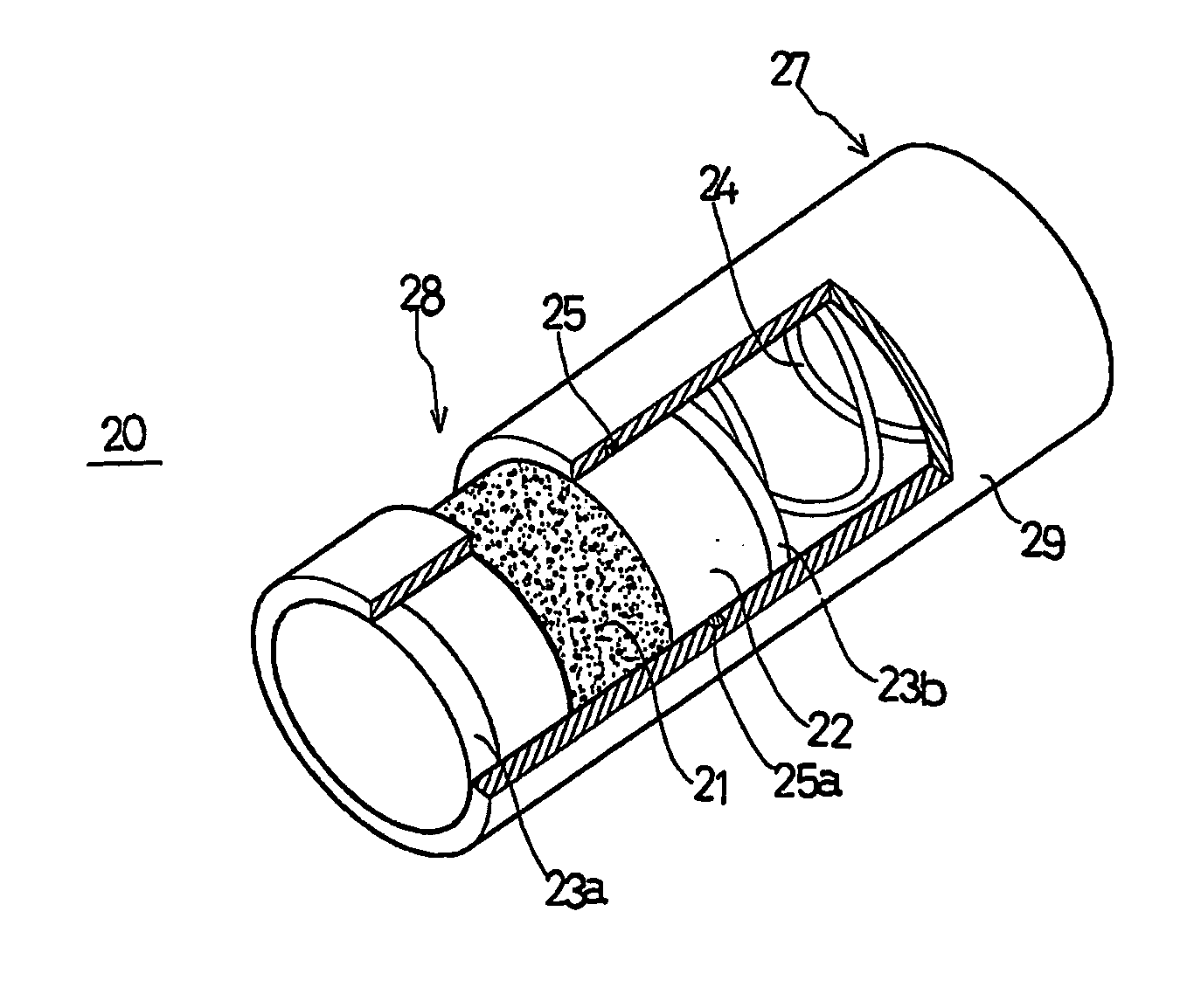
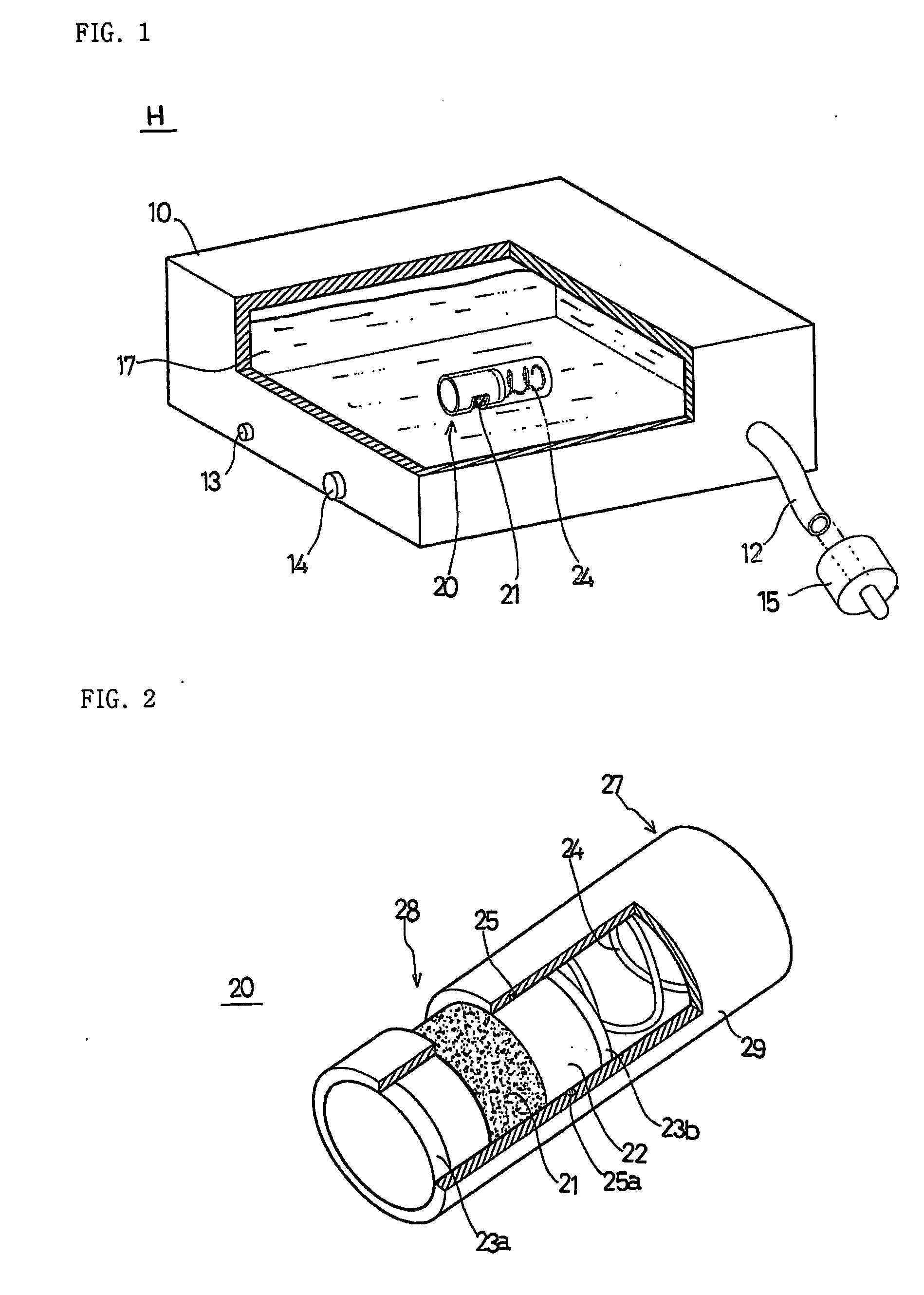
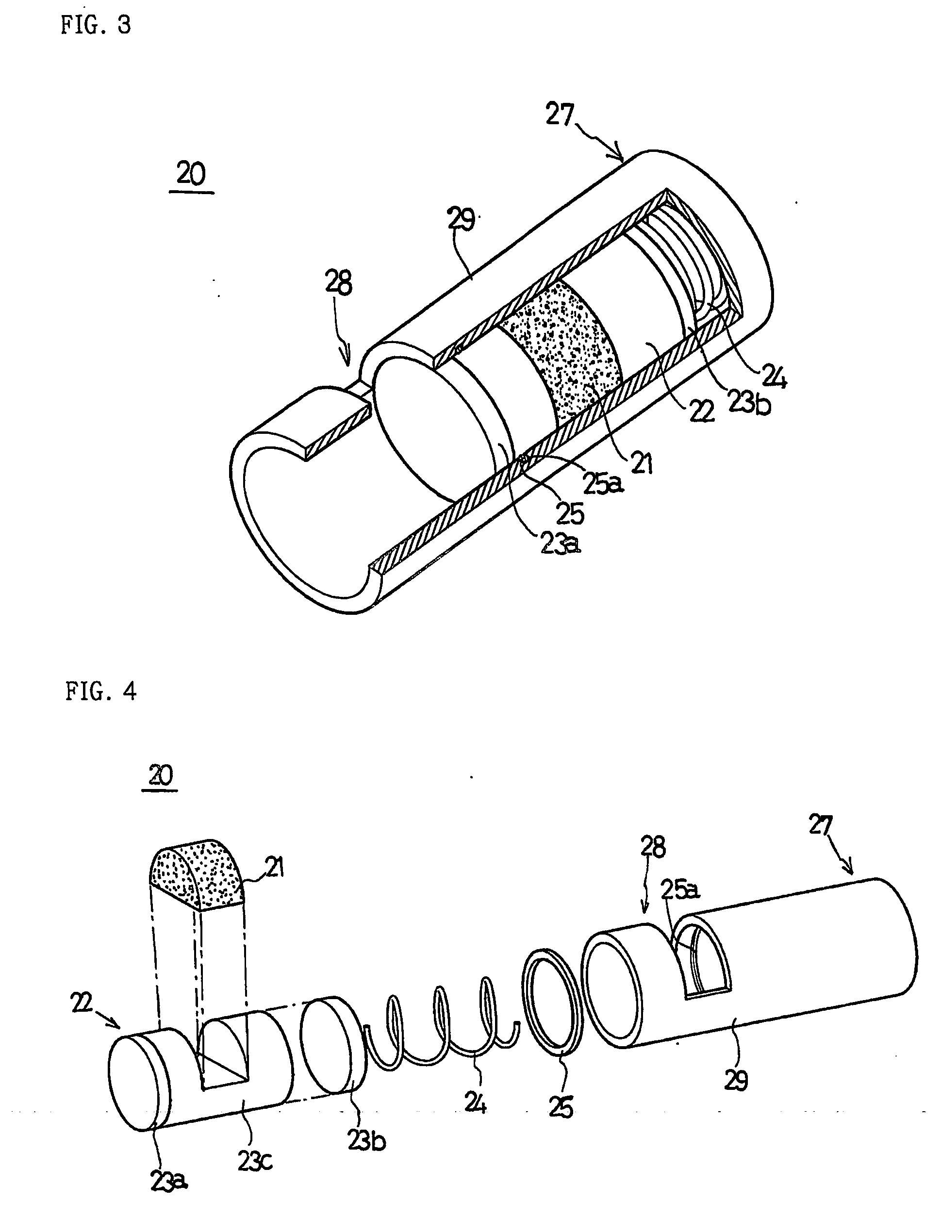
[0032] More specifically, the hydrogen gas generator (H) of the present invention comprises a fuel tank 10 having a designated size for maintaining a hermetically sealed space, a hydrogen storing material fuel solution 17 contained in the fuel tank 10, and a catalyst 21 contacting the hydrogen storing material fuel solution 17 for generating hydrogen gas. The catalyst 21 fills a catalyst reactor 20 having a designated shape. FIG. 1 is a perspective view of the hydrogen gas generator, in which the fuel tank 10 is partially exploded in accordance with the present invention.

[0033] As shown in FIG. 1, the fuel tank 10 has the designated size for containing the fuel solution having a certain volume, and the size and shape of the fuel tank 10 vary according to the purpose and kind of the fuel tank 10. An outlet 12 for discharging hydrogen generated in the fuel tank 10 is formed in one side surface of the fuel tank 10, and a valve, such as a quick connector 15, is installed on the outlet 1...

second embodiment

[0065] More specifically, in the second embodiment shown in FIGS. 23 and 24, a stopper 60a is protruded from one end of the catalytic reactor 20, and a stopper-fixture 60b for fixing the stopper 60a is formed in the front end of the inside of the installation groove 60. A through hole 62 communicating with the inside of the fuel tank 10 is formed at a designated position of the inner circumference of the installation groove 60, the elastic means 24 is positioned on the bottom of the installation groove 60 inside the through hole 62, a through hole sealing member 26 for sealing the through hole 62 is combined with the elastic means 24, a hydrogen generation regulating hole 64 communicating with the inside of the fuel tank 10 for introducing a fluid of the fuel tank 10 is formed through the bottom of the installation groove 60, and the gas-liquid separating film 42 is installed in front of the hydrogen generation regulating hole 64 in the fuel tank 10.

[0066] As shown in FIG. 23, befor...

third embodiment

[0068] In the third embodiment shown in FIGS. 25 and 26, a catalyst exposure regulating portion 66 having a sealed space is extended from the end of the above-described catalytic reactor 20, i.e., the outer surface of the catalyst-fixing member 22. A hydrogen generation regulating hole 64′, which coincides with the hydrogen generation regulating hole 64 when the catalytic reactor 20 is inserted into the installation groove 60 and regulates the generation of hydrogen gas by moving the catalyst-fixing member 22 based on the increase and decrease of the inner pressure of the fuel tank 10, is formed through a designated position of the catalyst exposure regulating portion 66.

[0069] The hydrogen gas generator (H) of the third embodiment is the same as the hydrogen gas generator (H) of the second embodiment in that the generation of the hydrogen gas and the interruption of the hydrogen gas are achieved by the increase and decrease of the inner pressure of the fuel tank 10. However, in the...


PUM

PropertyMeasurementUnit
pressureaaaaaaaaaa
volumeaaaaaaaaaa
pressureaaaaaaaaaa

Abstract

Disclosed is a self-regulating hydrogen gas generator for a hydrogen fuel cell. The self-regulating hydrogen gas generator includes a fuel tank, defining an inner space having a designated volume, provided with a hydrogen outlet communicating the inner space, a fuel solution, containing a hydrogen storing material, stored in the fuel tank, and a catalyst contacting the fuel solution for generating hydrogen gas, wherein the catalyst fills a catalytic reactor, provided with a closed portion for interrupting the contact between the catalyst and the fuel solution, and an opened portion contacting the fuel solution, so that the generation and interruption of hydrogen gas are actively regulated based on the increase and decrease of the pressure of the fuel tank.

Description

TECHNICAL FIELD [0001] The present invention relates to a self-regulating hydrogen gas generator, and more particularly to a hydrogen gas generator for actively regulating the generation of hydrogen gas due to variation in pressure of a fuel tank based on the amount of hydrogen gas generated in the fuel tank regardless of any external force. BACKGROUND ART [0002] Recently, industrial development has improved quality of life, but the rapid increase of energy demand causes serious problems such as environmental pollution and exhaustion of fossil fuels. [0003] All the countries of the world put forth great effort into the development of alternative energy sources to protect against possible exhaustion of fossil fuels, including petroleum. Particularly, the conventional use of fossil fuels causes serious environmental (air) pollution, thereby accelerating global warming and the destruction of environment. It is known that the main factors contaminating the atmosphere are nitric oxides, ...

Claims


Application Information

Patent Timeline
Patent Type & Authority Applications(United States)
IPC IPC(8): C10J3/68C10J1/207B01J7/02B01J14/00C01B3/06
CPCB01J7/02B01J14/005B01J2219/00162B01J2219/00164B01J2219/0027C01B3/06C01B3/065F17C11/005H01M8/04208H01M8/04216H01M8/065Y02E60/321Y02E60/50Y02E60/362Y02E60/32Y02E60/36
Inventor CHA, SEUNG SIKPARK, JEONG GUN
Owner TEMCO
Why Eureka
Try Eureka