
Multimode optical fiber and method for manufacturing same

a multi-mode optical fiber and manufacturing method technology, applied in the field of improved multi-mode optical fibers, can solve the problems of increasing the total deposition time and reducing productivity, and achieve the effects of improving the uniformity of radial temperature within the tube, improving the uniformity of geo2 concentration, and reducing the number of index-ripples

Inactive Publication Date: 2006-08-24
OFS FITEL LLC
View PDF7 Cites 3 Cited by
  • Summary
  • Abstract
  • Description
  • Claims
  • Application Information

AI Technical Summary

Benefits of technology

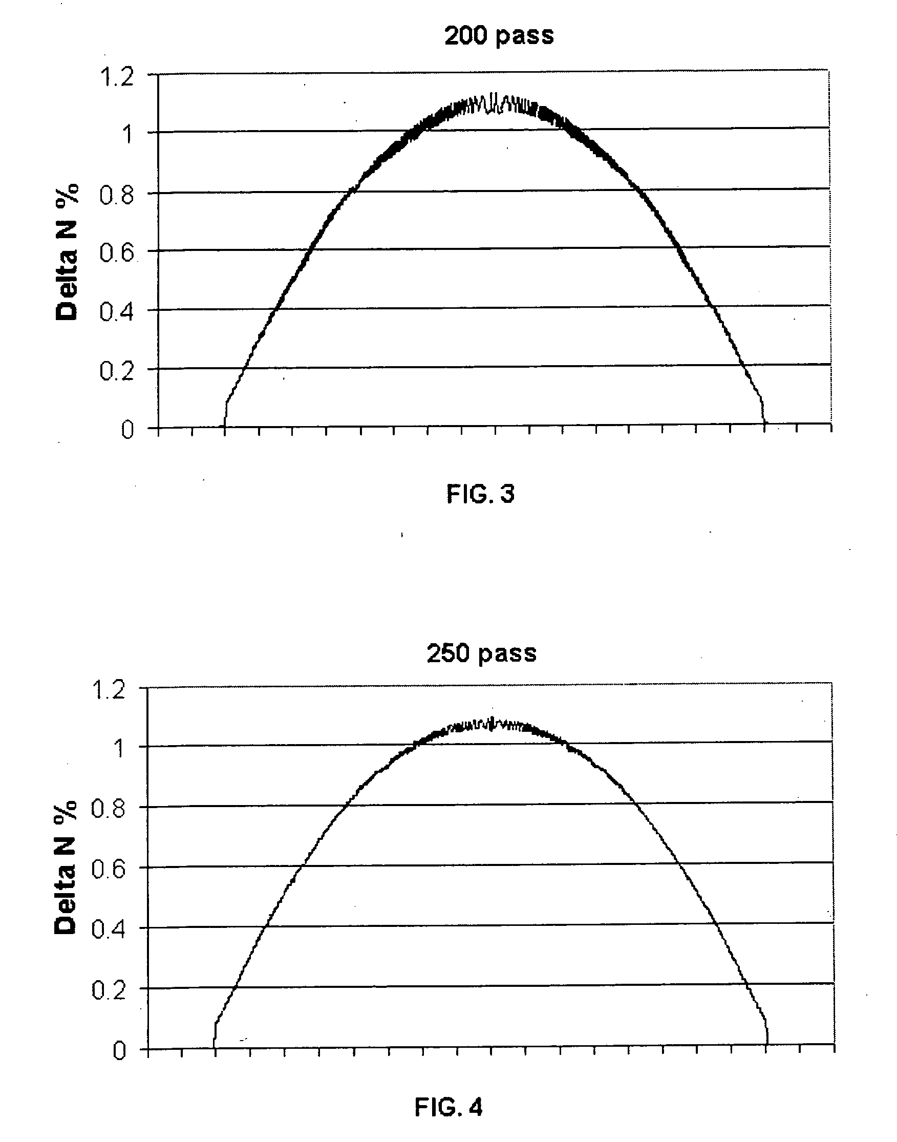
The present invention relates to an improved method for depositing glass layers for high-bandwidth optical fibers. The method reduces rippling in the refractive-index profile of the fibers, which results from non-uniformities in dopant concentration. This is achieved by controlling the refractive-index profile of the fibers during the deposition process. The method also reduces the number of deposition passes, which decreases productivity. The resulting fibers have a smoother refractive-index profile with smaller index-ripples, and a tunable refractive-index profile for high-bandwidth applications. The method includes controlled grading of the index of the glass fibers by doping during soot formation using a gaseous dopant-bearing compound. The presence of N2O or NF3 or CO during deposition improves the uniformity of the GeO2 concentration within each resulting glass layer.

Problems solved by technology

Clearly, such a conventional technique decreases productivity, because as the number of passes increases the total deposition time increases.

Method used


Image

  • Multimode optical fiber and method for manufacturing same
  • Multimode optical fiber and method for manufacturing same
  • Multimode optical fiber and method for manufacturing same

Examples


example

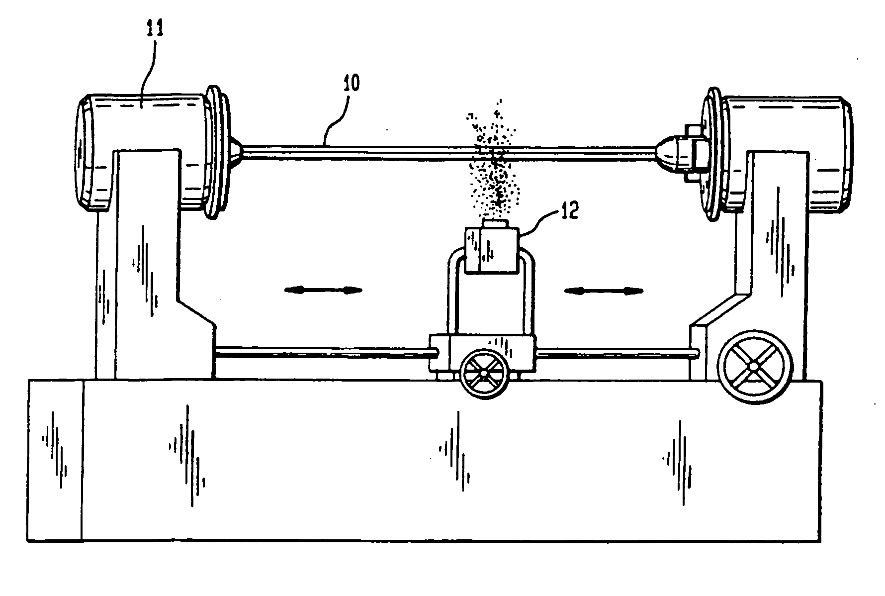
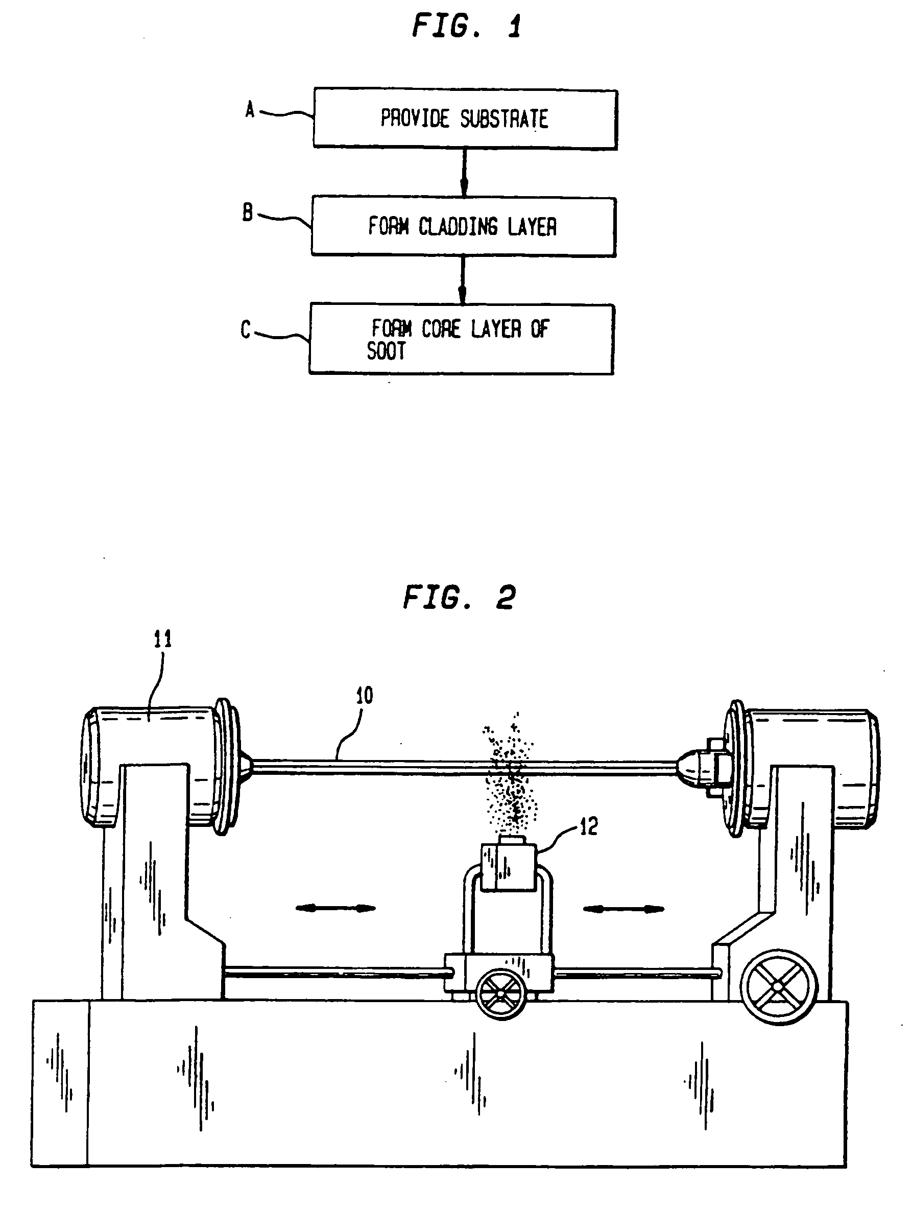
[0042] Multiple pure silica cladding sub-layers (in composite forming a cladding layer) are deposited in a silica tube by flowing 1.5 g / min of SiCl4 in 850 cc / min of O2 and 400 cc / min of He. For each cladding sub-layer, a torch traverses the tube to heat the tube to a temperature of 2050° C. The SiCl4 oxidizes into silica particles, which deposit on the interior wall of the tube by thermophoresis. The silica particles sinter to form a thin glass layer upon heating by the torch as the torch passes along the length of the tube. Multiple core sub-layers (in composite forming a core layer) are deposited next by flowing 1.2 to 3.6 g / min of SiCl4 in 4000 to 5000 cc / min of O2, 500 to 2000 cc / min of He, and 1000 to 5000 cc / min of N2O. Also flowing in the tube is GeCl4 in an amount that ranges from 0.04 to 0.72 g / min and POCl3 in an amount that ranges from 0.03 to 0.09 g / min, depending on the desired index of the sub-layer being deposited. For each core sub-layer, the torch traverses the tub...


PUM

PropertyMeasurementUnit
diametersaaaaaaaaaa
diametersaaaaaaaaaa
temperatureaaaaaaaaaa

Abstract

An improved MCVD process reduces a rippling structure in the refractive-index profile of a graded-index, multiple-mode optical fiber by incorporating N2O, CO, or NF3 gas in the gas stream during deposition of a soot sub-layer from which the optical fiber is formed. The soot sub-layer is sintered to form a glass sub-layer during deposition of a subsequent soot sub-layer. A dopant species is incorporated in each soot sub-layer during deposition. Fibers made from the doped glass sub-layers have a graded refractive-index profile that is near-parabolic in shape and that has significantly reduced rippling compared to profiles observed for fibers prepared conventionally.

Description

BACKGROUND OF THE INVENTION [0001] 1. Field of the Invention [0002] The present invention relates generally to an improved multimode (MM) optical fiber made by a chemical vapor deposition (CVD) process. More particularly, the present invention relates to a graded-index (GI) MM optical fiber made by a modified CVD (MCVD) process. [0003] 2. Related Art [0004] Optical communications systems generally operate in the visible or near-visible region of the electromagnetic spectrum, and generally utilize cladded glass fibers as the transmission medium. Such fibers usually have at least two sections: a core and a cladding layer surrounding the core. Generally, the cladding layer has a lower refractive index (referred to herein as “index”) relative to the core. The difference in index between the core and the cladding layer may be in the range of about 0.005 to 0.05. [0005] Fibers for single-mode transmission are characterized by a core that is sufficiently small in diameter to efficiently ac...

Claims


Application Information

Patent Timeline
Patent Type & Authority Applications(United States)
IPC IPC(8): G02B6/02C03B37/07C03B37/075C03B37/018
CPCC03B37/01807G02B6/0288Y02P40/57A61N2005/1087H01T23/00H05B1/02H05B1/0272H05B2203/035
Inventor BAUMGART, JERRY W.OULUNDSEN, GEORGE E. IIIYAN, MAN FEI
Owner OFS FITEL LLC
Learn More