Switching power supply apparatus

a technology of switching power supply and power supply core, which is applied in the direction of electric variable regulation, process and machine control, instruments, etc., can solve the problems of increasing the loss of efficiency, increasing and reducing the rate of use of the core of the transformer t, so as to reduce the noise and size of the switching power supply apparatus, improve the rate of use of magnetic flux, and reduce the size of the transformer

Inactive Publication Date: 2006-08-24
SANKEN ELECTRIC CO LTD
View PDF4 Cites 53 Cited by
  • Summary
  • Abstract
  • Description
  • Claims
  • Application Information

AI Technical Summary

Benefits of technology

[0024] As explained above, the present invention provides a low-noise, high-efficiency switching power source apparatus capable of achieving zero-voltage switching and making the rise and fall of a voltage gentler due to a resonance action.
[0025] The present invention can improve the rate of use of magnetic flux of the core of a transformer, to thereby reduce the size of the transformer. By adjusting the ca

Problems solved by technology

If the conversion frequency is increased to reduce the size of the apparatus, the loss increases to deteriorate efficienc

Method used


Image

  • Switching power supply apparatus
  • Switching power supply apparatus
  • Switching power supply apparatus

Examples


first embodiment

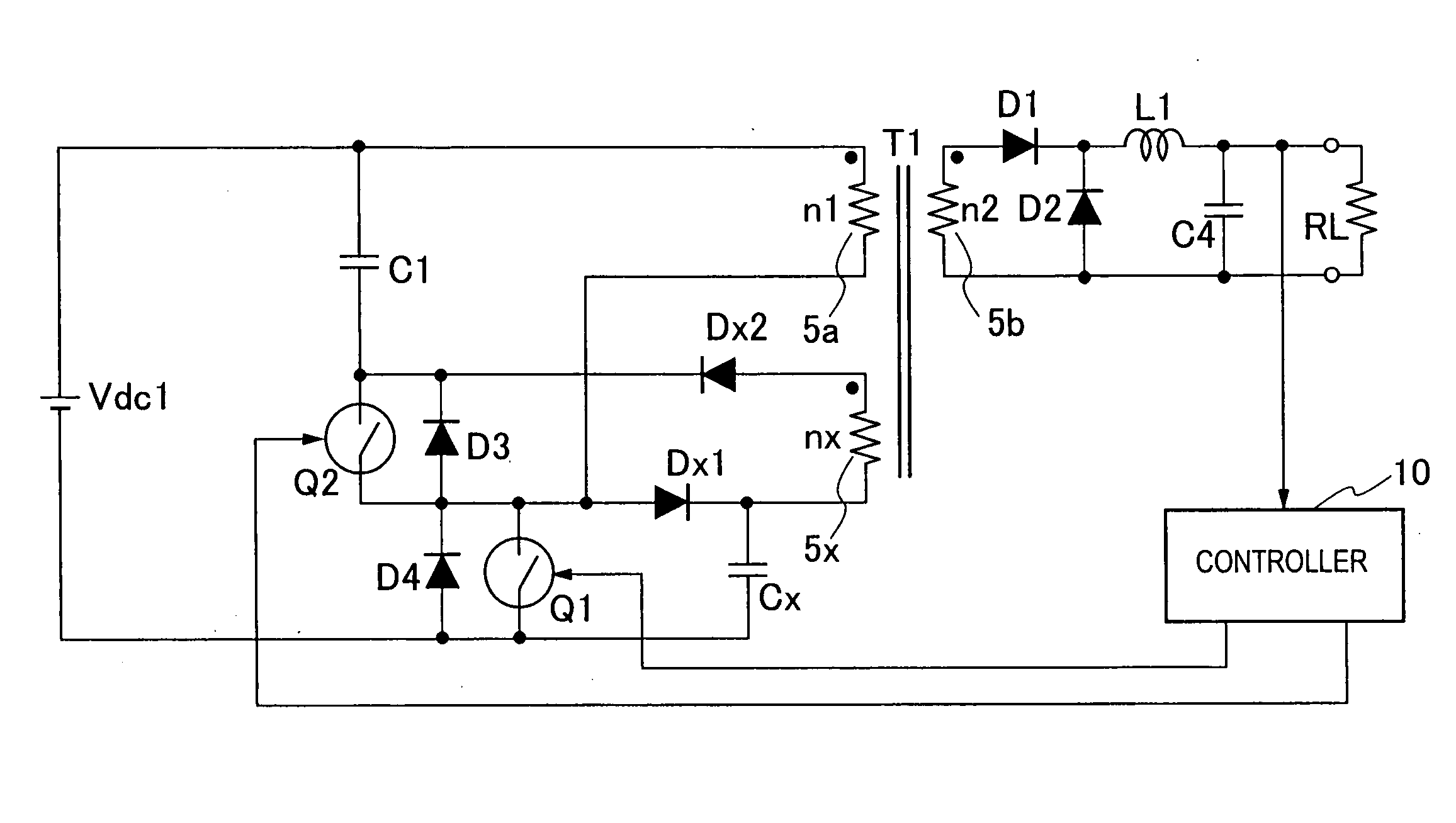
[0046] A switching power source apparatus according to the first embodiment arranges an auxiliary winding for a transformer. When a main switch is turned on, a snubber capacitor connected through a diode is discharged through the auxiliary winding to a clamp capacitor. When the main switch is turned off, the snubber capacitor is charged to make the inclination of a voltage increase gentle at the time when the main switch is turned off. At the same time, an auxiliary switch connected in series with the clamp capacitor is turned on, to bias magnetic flux of the transformer toward a minus side to expand the range of change of magnetic flux and the auxiliary switch is turned off to make the main switch conduct zero-voltage switching (ZVS) when an exciting current increases. In this way, this embodiment establishes ZVS, improves efficiency, decreases noise, and reduces the size of the transformer.

[0047]FIG. 5 is a circuit diagram showing the switching power source apparatus according to...

second embodiment

[0071] Next, a switching power source apparatus according to the second embodiment of the present invention will be explained. FIG. 13 is a circuit diagram showing the switching power source apparatus according to the second embodiment. The switching power source apparatus of the second embodiment of FIG. 13 differs from the switching power source apparatus of the first embodiment of FIG. 5 in a circuit on the secondary side of a transformer T2, and therefore, only this part will be explained.

[0072] The transformer T2 has a primary winding 5a (the number of turns of n1), a secondary winding 5b (the number of turns of n2), and a tertiary winding 5c (the number of turns of n3).

[0073] Each end of a series circuit consisting of the secondary winding 5b and tertiary winding 5c of the transformer T2 is connected to a series circuit consisting of a diode D6 and a capacitor C4. A node between the secondary winding 5b and the tertiary winding 5c and a node between the diode D6 and the capa...

third embodiment

[0083] Next, a switching power source apparatus according to the third embodiment of the present invention will be explained. FIG. 15 is a circuit diagram showing the switching power source apparatus according to the third embodiment. The switching power source apparatus of the third embodiment of FIG. 15 differs from the switching power source apparatus of the first embodiment of FIG. 5 in a circuit on the secondary side of a transformer T3, and therefore, only this part will be explained.

[0084] A core of the transformer T3 is wound with a primary winding 5a and a secondary winding 5b (the number of turns of n2) that is of an opposite phase relative to the phase of the primary winding 5a. A first end of the secondary winding 5b is connected to an anode of a diode D1. A cathode of the diode D1 and a second end of the secondary winding 5b are connected to a capacitor C4. The diode D1 and capacitor C4 form a rectifying-smoothing circuit. The capacitor C4 smoothes a rectified voltage ...


PUM


Abstract

A switching power source apparatus can reduce the size of a transformer and realize the zero-voltage switching of a switch. The apparatus is compact, highly efficient, and low in noise. The apparatus has a series circuit connected to each end of a DC power source (Vdc1) and including a primary winding (5a) of a transformer (T) and a main switch (Q1), a rectifying-smoothing circuit to rectify and smooth a voltage that is outputted from a secondary winding (5b) when the main switch (Q1) is turned on, a series circuit connected to each end of the primary winding (5a) and including an auxiliary switch (Q2) and a clamp capacitor (C1), a series circuit connected to each end of the main switch (Q1) and including a diode (Dx1) and a snubber capacitor (Cx), a series circuit connected to a node between the diode (Dx1) and the snubber capacitor (Cx) and a node between the auxiliary switch (Q2) and the clamp capacitor (C1) and including an auxiliary winding (5x) and a diode (Dx2), and a control circuit (10) to alternately turn on/off the main switch (Q1) and auxiliary switch (Q2). When the main switch (Q1) is turned on, the snubber capacitor (Cx) is discharged through the auxiliary winding (5x) to the clamp capacitor (C1). When the main switch (Q1) is turned off, the snubber capacitor (Cx) is charged, to relax the inclination of a voltage increase of the main switch (Q1).

Description

TECHNICAL FIELD [0001] The present invention relates to a switching power source apparatus that is highly efficient, compact, and low noise. [0002]FIG. 1 is a circuit diagram showing a switching power source apparatus type according to a related art (Non-Patent Document 1 and Non-Patent Document 2). In the switching power source apparatus of FIG. 1, a DC power source Vdc1 is connected through a primary winding 5a (the number of turns of n1) of a transformer T to a main switch Q1 that is made of, for example, a MOSFET (hereinafter referred to as FET). Each end of the primary winding 5a is connected to a parallel circuit composed of a resistor R2 and a capacitor C2 and a diode D3 that is connected in series with the parallel circuit. The main switch Q1 is turned on / off by PWM control of a control circuit 100. [0003] The primary winding 5a and a secondary winding 5b of the transformer T are wound to generate in-phase voltages. The secondary winding 5b (the number of turns of n2) is con...

Claims


Application Information

Patent Timeline
IPC IPC(8): H02H7/122H01F27/28H01F27/24H01F27/38H01F30/00H01F38/08H02M3/28H02M3/335
CPCH01F27/38H01F38/08H02M3/33569H02M3/01
Inventor TSURUYA, MAMORU
Owner SANKEN ELECTRIC CO LTD
Why Eureka
Try Eureka