Dynamic activation for an atomic force microscope and method of use thereof

a technology of dynamic activation and atomic force microscope, which is applied in the direction of mechanical roughness/irregularity measurement, instruments, measurement devices, etc., can solve the problems of limited throughput per machine, speed of atomic force microscope is typically far too slow for production applications, and the use of afm is more extensive, so as to improve the speed and ease of use of atomic force microscope, the effect of improving efficiency and cost-effectiveness

Inactive Publication Date: 2006-08-31
BRUKER NANO INC
View PDF17 Cites 30 Cited by
  • Summary
  • Abstract
  • Description
  • Claims
  • Application Information

AI Technical Summary

Benefits of technology

[0027] The preferred embodiment of the present invention increases the speed and ease of use of an AFM by including an amplitude detection circuit to dynamically control the cantilever drive signal in the amplitude domain. In particular, by demodulating the cantilever response before it is used to modify the drive signal to the cantilever, the need to adjust the transfer function of a Q modifying filter in the feedback path is eliminated, thus making operation more cost-effective, efficient, and allowing ready substitution of different cantilevers.
[0028] Similar to previous embodiments, the present invention preferably combines an AFM Z position actuator and a self-actuated Z position cantilever (both operable in cyclical mode and contact mode), with appropriately nested feedback control circuitry to achieve high-speed imaging and accurate Z position measurements. The feedback signals applied to each of the actuators can be independently monitored to indicate the topography of the sample surface, depending upon the scan rate and sample topography.
[0029] According to another aspect, the lower frequency topography features of a sample, including the slope of the sample surface, are followed by a standard Z actuator while the high frequency components of the surface topography are followed by the self-actuated cantilever. Preferably, two feedback loops are employed. The first feedback loop controls the self-actuated cantilever to maintain a relatively constant force between the tip of the cantilever and the sample surface. The second feedback loop controls the standard Z actuator, at a lower speed than the first feedback loop and serves either (1) to keep the self-actuated cantilever within its operating Z range or (2) to maintain the linearity of the positioning sensitivity of the cantilever when following low frequency topography. This embodiment also allows for the standard Z actuator to be exclusively used for accurate height measurements when the scan rate is sufficiently lowered, typically less than 500 μm / sec.

Problems solved by technology

A limiting factor to the more extensive use of the AFM is the limited throughput per machine due to the slow imaging rates of AFMs relative to competing technologies.
Although it is often desirable to use an AFM to measure surface topography of a sample, the speed of the AFM is typically far too slow for production applications.
As a result, using AFM technology for surface measurement typically yields a system that has a high cost per measurement.
The frequency at which the total phase lag of all the components in the system is large enough for the loop to be unstable is the ultimate bandwidth limit of the loop.
Nevertheless, in contact mode, the Z position actuator still limits the Z-position bandwidth.
Such devices generally have a mechanical resonance far below that of the AFM cantilever brought in contact with the sample, typically around 1 kHz, thus limiting the Z-position bandwidth.
Nevertheless, such an AFM exhibits new problems with the Z positioning which were not concerns with other known AFMs.
In addition, because the positioning sensitivity of each cantilever is different, the AFM requires recalibration whenever the probe is changed due to a worn or broken tip.
Further, the sensitivity in some cases exhibits undesirable non-linearity at low frequencies.
These problems can make the Z actuator integrated with the cantilever a less than optimal choice for general use as the Z actuator in commercial AFMs.
Furthermore, notwithstanding the above, in many AFM imaging applications, the use of contact mode operation is unacceptable.
Friction between the tip and the sample surface can damage imaged areas as well as degrade the tip's sharpness.
However, the bandwidth limitations associated with cyclical mode detection are typically far greater than those associated with contact mode operation.
One potential problem associated with cyclical mode operation is that the bandwidth of the response to this force is proportional to 1 / Q (where Q is the “quality factor” of the natural resonance peak), while the force sensitivity of the measurement is proportional to the Q of the natural resonance peak.
However, reducing the Q of the cantilever correspondingly reduces force detection sensitivity, which thereby introduces noise into the AFM image.
A further contributing factor to less than optimal scan rates in cyclical mode operation is the fact that the amplitude error signal has a maximum magnitude.
Finally, the maximum gain of the control loop in cyclical mode is limited by phase shifts, thus further limiting the loop bandwidth.
As a result, AFM technology posed a challenging problem if the scan rate in cyclical mode was to be increased significantly.
Overall, the Mertz system is complex and produces marginally reliable measurements at undesirably slow speeds.
This adjustment can be difficult to automate and typically requires either extensive computer processing or the intervention of an expert user.

Method used


Image

  • Dynamic activation for an atomic force microscope and method of use thereof
  • Dynamic activation for an atomic force microscope and method of use thereof
  • Dynamic activation for an atomic force microscope and method of use thereof

Examples


Embodiment Construction

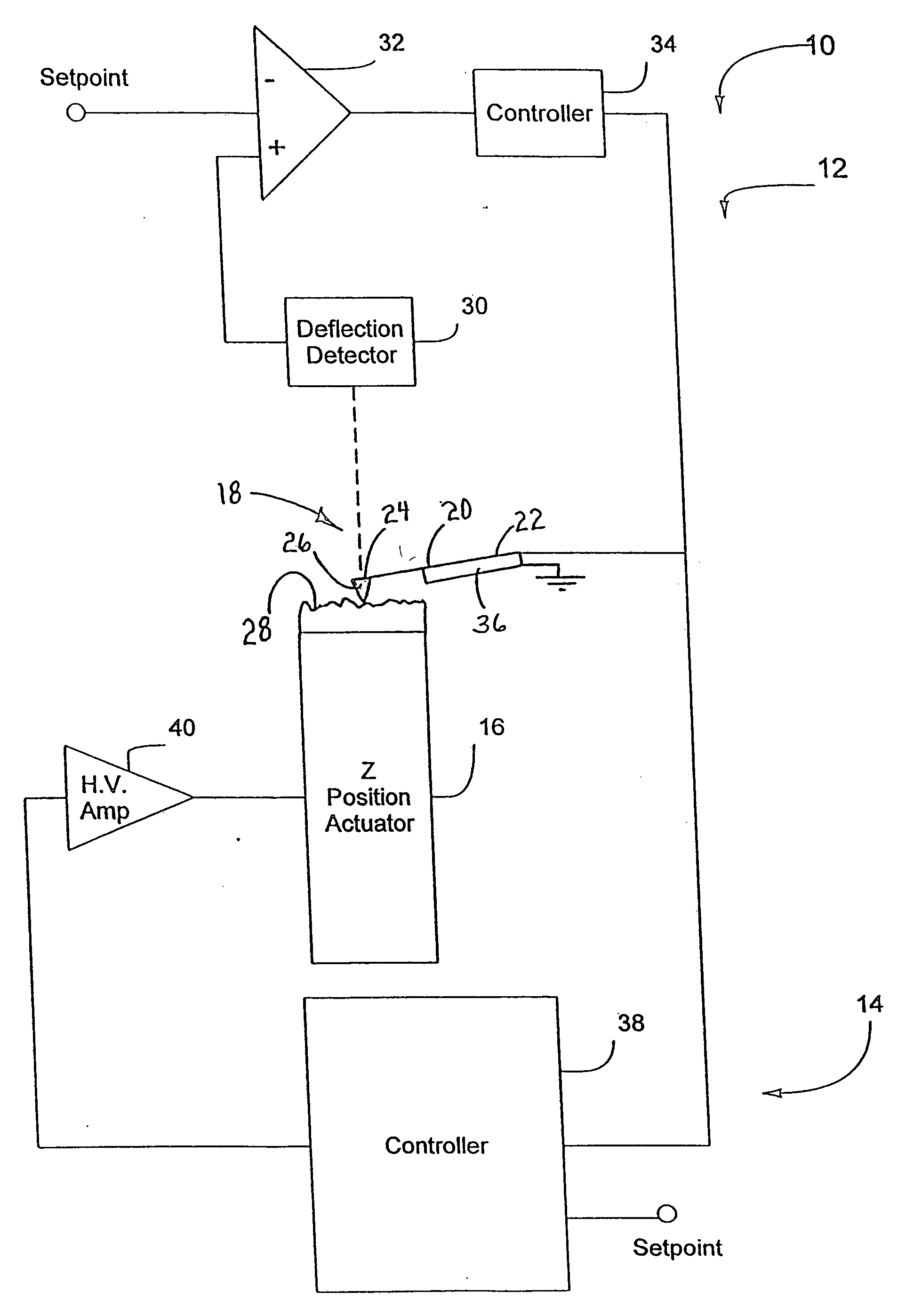
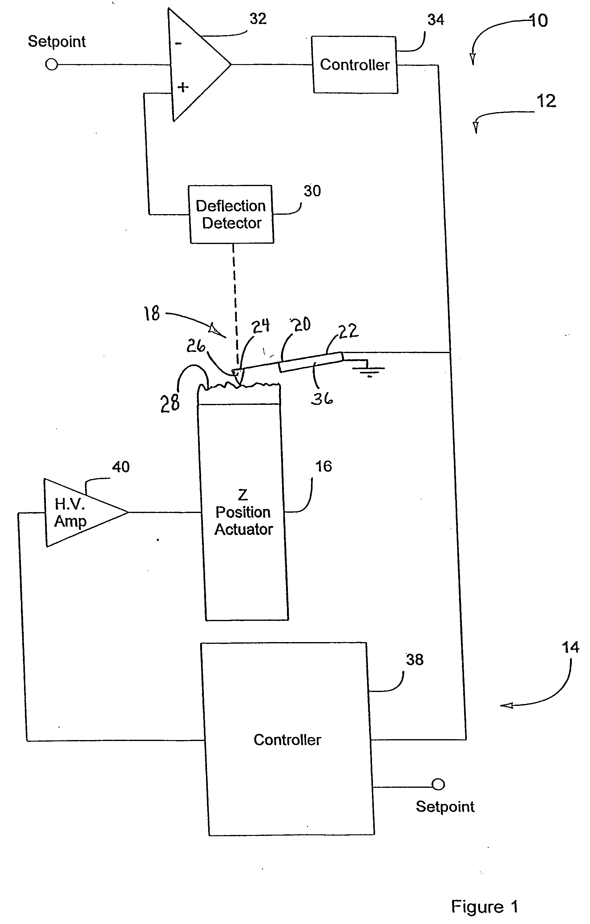
[0056] Referring to FIG. 1, an AFM 10 according to the present invention, which is configured for contact mode operation, is shown. AFM 10 includes two feedback loops 12 and 14 that control an AFM Z position actuator 16 and a probe assembly 18, respectively. Probe assembly 18 includes a self-actuated cantilever 20 having a tip 26 that interacts with a sample during scanning. When scanning in contact mode, tip 26 generally continually contacts the sample, only occasionally separating from the sample, if at all. For example, at the end of a line scan tip 26 may disengage the sample surface. While it scans the surface of the sample, cantilever 20 responds to the output of feedback loop 12 to ultimately map the topography of the surface of the sample, as described in further detail below.

[0057] Cantilever 20 includes a fixed end 22 preferably mounted to an AFM mount (not shown) and a free distal end 24, generally opposite fixed end 22, that receives tip 26. In operation, the interactio...


PUM


Abstract

A scanning probe microscope method and apparatus that modifies imaging dynamics using an active drive technique to optimize the bandwidth of amplitude detection. The deflection is preferably measured by an optical detection system including a laser and a photodetector, which measures cantilever deflection by an optical beam bounce technique or another conventional technique. The detected deflection of the cantilever is subsequently demodulated to give a signal proportional to the amplitude of oscillation of the cantilever, which is thereafter used to drive the cantilever.

Description

CROSS-REFERENCE TO A RELATED APPLICATION [0001] The present application is a divisional of United States patent application Ser. No. 10 / 752,235, which is a divisional of United States patent application Ser. No. 09 / 904,913, filed on Jul. 13, 2001, entitled DYNAMIC ACTIVTION FOR AN ATOMIC FORCE MICROSCOPE AND METHOD OF USE THEREOF, issued as U.S. Pat. No. 6,672,144, which is a continuation-in-part of United States patent application Ser. No. 09 / 476,163, filed on Dec. 30, 1999, which is a continuation in-part of United States patent application Ser. No. 09 / 280,160, filed on Mar. 29, 1999, both of these latter applications entitled ACTIVE PROBE FOR AN ATOMIC FORCE MICROSCOPE AND METHOD OF USE THEREOF, and now issued as U.S. Pat. Nos. 6,530,266 and 6,189,374, respectively, and each of which is expressly incorporated by reference herein.BACKGROUND OF THE INVENTION [0002] 1. Field of the Invention [0003] The present invention relates to atomic force microscopes (AFMs) and, more particular...

Claims


Application Information

Patent Timeline
Patent Type & Authority Applications(United States)
IPC IPC(8): G01B5/28G01Q10/00G01Q10/06G01Q20/02G01Q60/24G01Q60/34
CPCB82Y35/00G01Q10/065G01Q60/34Y10S977/85Y10S977/881Y10S977/863Y10S977/86
Inventor ADDERTON, DENNIS M.MINNE, STEPHEN C.
Owner BRUKER NANO INC
Why Eureka
Try Eureka