Complementary metal-oxide-semiconductor image sensor and method for fabricating the same

a metal-oxide-semiconductor and image sensor technology, applied in the field of complementary metal-oxide-semiconductor (cmos) image sensor, can solve the problems of critical error in the detection of electric signals, display screen whitening in a dark state, and use of polycide gate structure does not provide the intended level of operation speed

Active Publication Date: 2006-08-31
INTELLECTUAL VENTURES II
View PDF11 Cites 23 Cited by
  • Summary
  • Abstract
  • Description
  • Claims
  • Application Information

AI Technical Summary

Benefits of technology

[0023] In accordance with a further aspect of the present invention, there is provided a method for fabricating a complementary metal-oxide-semiconductor (CMOS) image sensor, including: forming devices configuring a unit pixel and CMOS devices for processing data outputted from the unit pixel in a pixel region and a logic region of a semi-conductor layer, respectively; forming a self-aligned silicide blocking layer covering the pixel region and opening gate electrodes and source / drain regions of the logic region; forming a transition metal layer over the pixel region and the logic region; performing a rapid thermal annealing process, thereby forming a self-aligned silicide layer; and removing a non-reacted portion of the transition metal layer formed on the self-aligned silicide blocking layer.
[0024] In accordance with another further aspect of the present invention, there is provided a method for fabricating a complementary metal-oxide-semiconductor (CMOS) image sensor, including: forming devices configuring a unit pixel including a buried photodiode and a floating diffusion region and CMOS devices for processing data outputted from the unit pixel in a pixel region and a logic region of a semi-conductor layer, respectively; forming a self-aligned silicide blocking layer over a region extending from the buried photodiode to the floating diffusion region; forming a transition metal layer over the pixel region and the logic region; performing a rapid thermal process, thereby forming a self-aligned silicide layer on the pixel and logic regions except for the region where the self-aligned silicide blocking layer is formed; and removing a non-reacted portion of the transition metal layer formed on the self-aligned silicide blocking layer.

Problems solved by technology

However, in a sub-0.25 μm CMOS image sensor, the usage of the polycide gate structure does not provide an intended level of the operation speed.
Since the CMOS image sensor detects a change in an electric potential at the N+-type floating diffusion region in the pixel region and uses this detection as a data, the leakage current at the N+-type floating diffusion region becomes a cause for a critical error in the detection of electric signals.
Especially, the leakage current also causes degradation in a dark characteristic, which produces a defect in that a display screen becomes whitened in a dark state.
For this reason, the application of the silicide layer vulnerable to the leakage current to the floating diffusion region, which is a sensing node, may increase a probability of producing the above mentioned defect.
Also, although there is one suggested method to block the self-aligned silicide layer at the edge of the gate of the transfer transistor as shown in FIG. 3, in a 0.18 μm transistor, the size is too small to achieve good process reproducibility.
Furthermore, it may be difficult to form the self-aligned silicide layer uniformly on the gate if the self-aligned silicide layer formation is blocked at the edge of the gate.

Method used


Image

  • Complementary metal-oxide-semiconductor image sensor and method for fabricating the same
  • Complementary metal-oxide-semiconductor image sensor and method for fabricating the same
  • Complementary metal-oxide-semiconductor image sensor and method for fabricating the same

Examples


first embodiment

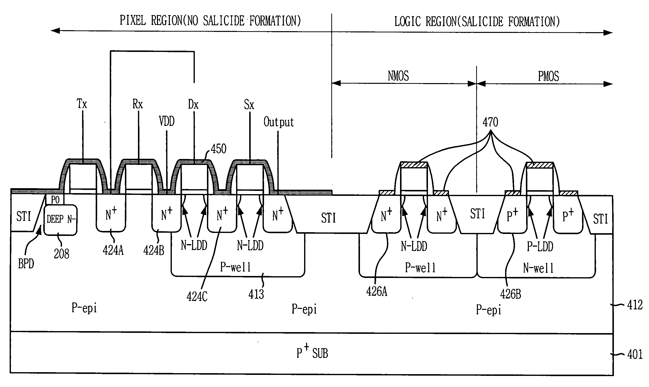
[0032]FIG. 4 is a cross-sectional view showing a CMOS image sensor in accordance with the present invention.

[0033] As shown, a salicide blocking layer 450 is formed on an entire pixel region including a buried photodiode BPD, an N+-type floating diffusion region 424A, which is a sensing node, and other devices configuring a unit pixel. In a logic region, a salicide layer 470 is formed on each gate of CMOS devices and highly doped N+-type impurity regions 426A and P+-type impurity diffusion regions 426B both serving as source / drain regions. Herein, the salicide layer is a self-aligned silicide layer.

[0034] If the silicide layer is formed on the source / drain regions in the logic region except for the pixel region, an operation speed of the CMOS image sensor that detects an electric signal corresponding to a photo-generated electric charge through a correlated double sampling mode can be enhanced. Also, being different from the conventional CMOS image sensor, the silicide layer does n...

second embodiment

[0043]FIG. 5 is a cross-sectional view showing a CMOS image sensor in accordance with the present invention.

[0044] In the CMOS image sensor according to the second embodiment of the present invention, a salicide blocking layer 550 is formed on a buried photodiode (BPD), a gate of a transfer transistor Tx, an N+-type floating diffusion region 524A and a portion of a gate of a reset transistor Rx, while a salicide layer 570 is formed over those devices configuring a unit pixel in a pixel region and over CMOS devices in a logic region. That is, the salicide layer 570 is formed on gates of a driver transistor Dx, a select transistor Sx, an NMOS transistor, a PMOS transistor, an N+-type drain junction 524B, N+-type impurity diffusion regions 524C and N+-type and P+-type impurity diffusion regions 526A and 526B. It should be noted that a CMOS image sensor fabrication method according to the second embodiment is identical to the CMOS image sensor fabrication method described in the first e...


PUM


Abstract

A complementary metal-oxide-semiconductor (CMOS) image sensor and a method for fabricating the same are provided. The CMOS image sensor includes: a pixel region provided with a plurality of unit pixels, each including a buried photodiode and a floating diffusion region; and a logic region provided with CMOS devices for processing data outputted from the unit pixels, wherein a self-aligned silicide layer is formed on gate electrodes and source/drain regions of the CMOS devices in the logic region while a self-aligned silicide blocking layer is formed over the pixel region.

Description

[0001] This application relies for priority upon U.S. Provisional Patent Application No. 60 / 657,323 filed on Feb. 28, 2005, the contents of which are herein incorporated by reference in its entirety.FIELD OF THE INVENTION [0002] The present invention relates to a complementary metal-oxide-semiconductor (CMOS) image sensor and a method for fabricating the same; and, more particularly, to a CMOS image sensor for improving reproducibility of a process in deep submicron technology below 0.25 μm as well as for satisfying optical characteristics of a pixel region and electrical characteristics of a logic region. DESCRIPTION OF RELATED ARTS [0003] Generally, a complementary metal-oxide-semiconductor (CMOS) image sensor is a device that converts an optical image into an electric signal through employing CMOS technology. Especially, the CMOS image sensor takes a switching mode that sequentially detects outputs by using MOS transistors fabricated so that one CMOS image sensor corresponds to o...

Claims


Application Information

Patent Timeline
Patent Type & Authority Applications(United States)
IPC IPC(8): H01L29/76H01L29/94H01L31/00H01L21/8238H01L27/092H01L27/146H04N5/335H04N5/357H04N5/369H04N5/374
CPCH01L27/14603H01L27/14609H01L27/14643H01L27/14689
Inventor LEE, JU-IL
Owner INTELLECTUAL VENTURES II
Why Eureka
Try Eureka