Three dimensional structure producing device and producing method

a three-dimensional structure and production device technology, applied in auxillary shaping apparatus, butter manufacture, manufacturing environment conditioning, etc., can solve the problems of reducing reducing the density of sintered portions, lowering the permeability of optical beams, etc., to achieve stable sintering, reduce light permeability, and reduce the effect of permeability to ligh

Inactive Publication Date: 2006-08-31
MATSUSHITA ELECTRIC WORKS LTD
View PDF9 Cites 163 Cited by
  • Summary
  • Abstract
  • Description
  • Claims
  • Application Information

AI Technical Summary

Benefits of technology

[0013] It is preferred that the optical beam-irradiating unit includes a beam shape-correcting unit for correcting a shape of the optical beam to form a generally round spot beam on a surface to be irradiated. In spite of irradiation in an oblique direction, the generally round spot beam is irradiated on the powdery layer, making it possible to conduct stable sintering.
[0014] If a fume blocking means permeable to light for blocking fumes generated during sintering from passing therethrough is interposed between the optical beam-irradiating range and a portion of the optical beam-irradiating unit from which the optical beam is emitted, a reduction in permeability to light can be positively prevented.
[0015] Also, if a fume capturing unit for capturing fumes is disposed immediately above the optical beam-irradiating range, a reduction in permeability to light that may be caused by the fumes can be further positively prevented.
[0016] The apparatus further includes a chamber for accommodating the table and the powdery layer-forming unit therein and a lid for opening and closing an opening defined in the chamber at a location immediately above the optical beam-irradiating range. By this construction, upon completion of the sintering and upon removal of unsolidified powder on the table, the three-dimensional object can be taken out from the chamber through the opening using, for example, a crane without causing any interference with the optical beam-irradiating unit, making it possible to prevent powder from scattering outside the chamber.
[0017] Further, upon completion of the sintering, the amount of fumes that remain in the chamber and the oxygen content within the chamber are measured while cleaning an atmosphere inside the chamber and replacing an atmospheric gas with air. When the amount of fumes and the oxygen content become less than respective predetermined values, the three-dimensional object is taken out through the opening, thereby preventing external environmental pollution.

Problems solved by technology

The fumes rise and adhere or stick to the window disposed immediately above them, thereby clouding up the window and lowering the permeability to the optical beam.
Accordingly, it becomes impossible to stabilize the sintering or increase the density of sintered portions, resulting in a reduction in strength of a three-dimensional object.
In this case, the repeatability for positioning of an optical axis is lost and, hence, the machining accuracy lowers considerably or adjusting work is needed whenever the shaping is conducted.
In this case, however, there is a good chance that the powder may be gotten caught in the movable table and incline it and, hence, it becomes difficult to ensure the repeatability for positioning of the optical axis, and a very complicated mechanism is needed.

Method used


Image

  • Three dimensional structure producing device and producing method
  • Three dimensional structure producing device and producing method
  • Three dimensional structure producing device and producing method

Examples


Embodiment Construction

[0037] Embodiments of the present invention are explained hereinafter with reference to the drawings.

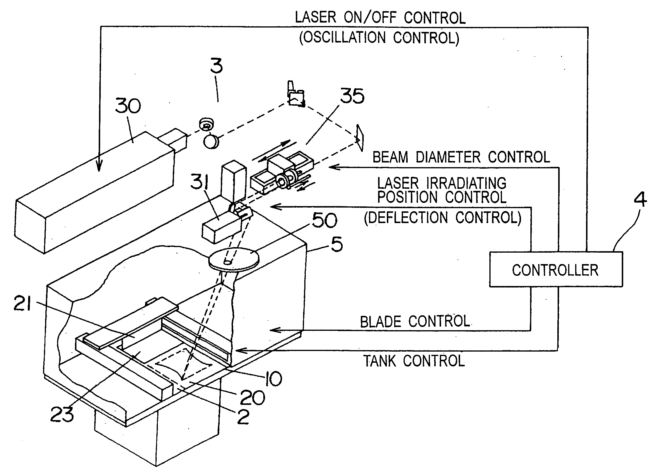
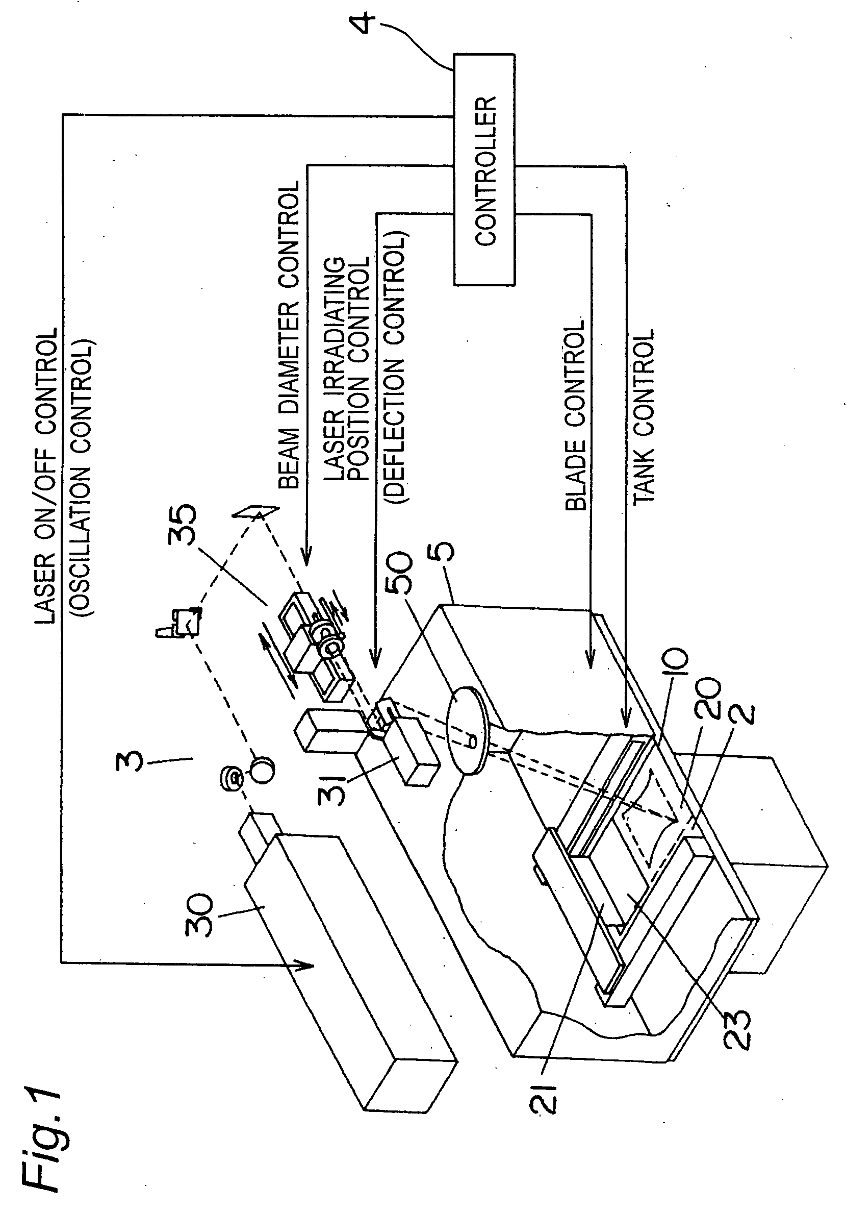
[0038]FIG. 1 depicts an apparatus for making a three-dimensional object according to the present invention, which includes a powdery layer-forming unit 2, an optical beam-irradiating unit 3, and a chamber 5 for accommodating the powdery layer-forming unit 2 therein.

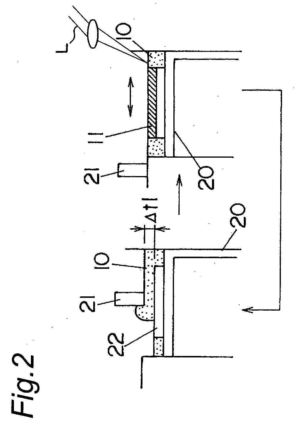
[0039] The powdery layer-forming unit 2 forms a powdery layer 10 of a predetermined thickness Δt1 on a table 20 that is vertically movable within an enclosed space by a cylinder, by supplying and leveling a metallic powdery material on the table 20 with the use of a leveling blade 21.

[0040] The optical beam-irradiating unit 3 irradiates a laser outputted from a laser generator 30 on the powdery layer 10 via a scanning optical system including a galvanomirror 31 and the like. The optical beam-irradiating unit 3 is disposed outside the chamber 5, and the optical beam emitted therefrom is irradiated on the powdery layer 10...


PUM

PropertyMeasurementUnit
weightaaaaaaaaaa
sizeaaaaaaaaaa
specific gravityaaaaaaaaaa

Abstract

An apparatus for making a three-dimensional object includes a powdery layer-forming unit for forming a powdery layer on a table and an optical beam-irradiating unit for irradiating an optical beam on a predetermined region of the powdery layer to sinter the predetermined region. The optical beam-irradiating unit is disposed at a position spaced from immediately above an optical beam-irradiating range to obliquely irradiate the optical beam on the powdery layer. Because fumes generated by irradiating and heating the powdery layer with the optical beam rise towards a position immediately above them, the optical beam is irradiated from the position spaced from immediately above the optical beam-irradiating range, thereby reducing a cloud of the optical beam-irradiating unit that may be caused by the fumes.

Description

TECHNICAL FIELD [0001] The present invention relates to a method of and apparatus for making a three-dimensional object by irradiating an optical beam on a powdery layer of inorganic or organic powdery material to form a sintered layer and by laminating sintered layers one above another. BACKGROUND ART [0002] A method of making a three-dimensional object by laminating sintered layers is known in, for example, Japanese Laid-Open Patent Publication No. 1-502890, wherein an optical beam (directional energy beam, for example, a laser) is first irradiated on a powdery layer formed on a table to form a sintered layer. The sintered layer thus obtained is then covered with a new powdery layer, on which the optical beam is irradiated to form a new sintered layer. These processes are repeatedly carried out to form a three-dimensional object in which a plurality of sintered layers are laminated one above another. [0003] This prior art includes a powder supply unit for supplying a powdery mater...

Claims


Application Information

Patent Timeline
Patent Type & Authority Applications(United States)
IPC IPC(8): B29C35/08B29C41/02B22F3/105B22F3/16B23K26/00B23K26/16B29C64/153B29C64/364B29C67/00C04B35/64
CPCB22F3/1055B29C67/0077B22F2003/1057B22F2003/1059B29C64/153B33Y30/00B33Y10/00Y02P10/25B22F10/28B22F12/90B22F10/36B22F12/70B22F12/44B22F10/32B22F10/77
Inventor ABE, SATOSHIFUWA, ISAOYOSHIDA, NORIOHIGASHI, YOSHIKAZUTOGEYAMA, HIROHIKOTAKENAMI, MASATAKASHIMIZU, TAKASHIUENAGA, SHUSHI
Owner MATSUSHITA ELECTRIC WORKS LTD
Why Eureka
Try Eureka