Frame design for reduced-size vehicle

a frame design and vehicle technology, applied in the direction of roofs, cycle equipment, cycles, etc., can solve the problems of inconvenient use of space, limited size of storage compartments, so as to facilitate vehicle buoyancy, facilitate vehicle buoyancy, and facilitate the creation of such interior cavities/storage compartments.

Inactive Publication Date: 2006-08-31
AMERICAN OFF ROAD TECH
View PDF99 Cites 40 Cited by
  • Summary
  • Abstract
  • Description
  • Claims
  • Application Information

AI Technical Summary

Benefits of technology

[0019] The present inventors have recognized that conventional reduced-size vehicles can be modified and improved in a variety of ways so as to address one or more of the above-discussed drawbacks of conventional reduced-size vehicles. In particular, the present inventors have recognized that, by modifying the internal frames of such vehicles so that the struts / tubes, castings, and stampings of the frames are not overly concentrated along the central longitudinal axes of the vehicles, it can become possible in at least some embodiments for large unobstructed interior cavities to be created within the vehicles at their front and rear ends, allowing for large interior storage compartments to be provided within the vehicles. The inventors have further recognized that in at least some embodiments the creation of such interior cavities / storage compartments can be further facilitated by utilizing shock absorbers that are vertically-oriented (as viewed from both front elevation and side elevation views) rather than obliquely-oriented as they extend between the frame and the wheels / axles. The inventors have additionally recognized that, in at least some embodiments, the filling of such interior storage compartments with items / materials will tend not to raise the vehicles' centers of gravity (and rather will tend to lower it), and / or that such storage compartments in certain embodiments can greatly facilitate vehicle buoyancy. Additionally, the inventors have recognized that the use of such modified internal frames can in at least some embodiments improve the manner in which the vehicles perform during accidents and / or respond to impacts.
[0020] Further, the present inventors have recognized that the cooling and exhaust systems of conventional reduced-size vehicles can be modified to improve the vehicles' design and performance. In particular, the present inventors have recognized that, in at least some embodiments, the placement of cooling and / or exhaust system components primarily within the mid-sections of the vehicles rather than in the front or rear sections of the vehicles not only is possible but also can be advantageous for several reasons. For example, the placement of cooling and / or exhaust system components within the mid-section of a vehicle in at least some embodiments can free up space within the front and rear sections of the vehicle, space which can be allocated to other vehicle structures such as the interior cavities / storage compartments discussed above. Further, the placement of cooling system components in the mid-section of a vehicle in at least some embodiments can reduce the risks of clogging / puncture of the cooling system components and / or can reduce the length of coolant lines that are utilized in those systems. Additionally, with respect to the exhaust system, the muffler when placed in the mid-section of a vehicle can be vertically-oriented and configured to resist backflow of water from the exhaust pipe back into the engine, as well as positioned so as to reduce the possibility of undesirable excessive heat dissipation occurring in relation to other components of the vehicle.

Problems solved by technology

As a result, such spaces typically are sufficient only for transporting small items such as a pair of gloves, a tow strap, or an emergency tool kit.
Further, these spaces often are inconvenient to use, for example, because the ports / doors are located at low or otherwise difficult-to-access locations (e.g., under the seat), or because the doors are at low levels and lack seals to prevent the entry of water into the spaces.
Although at least one manufacturer, Bombardier, has integrated a somewhat larger, 8 gallon storage compartment into the front end of at least one of its ATV models (e.g., the 1999 Traxter ATV), this storage compartment is still limited in size due to the frame of the ATV and due to the positioning of the front shock absorbers of the vehicle, and there is no comparable storage compartment in the rear of the ATV due to the movement of certain components from the front end of the vehicle to the rear end of the vehicle to provide sufficient space for the front storage compartment.
Also, although at least one other manufacturer, Arctic Cat, has integrated a somewhat larger, 8-10 gallon storage compartment into the rear end of at least one of its ATV models, this storage compartment is still limited in size due to the configuration of the vehicle frame and the positioning of the rear shock absorbers, as well as difficult to access insofar as it only occupies a region that is below the cargo rack accessible from behind the vehicle.
Although reduced-size vehicles with the above-described cargo rack and supplemental container features continue to increase in popularity, such conventional vehicles nevertheless have several limitations.
First, the attachment of items / materials to the cargo racks is often challenging due to the need for additional ropes or cords or special clips to fasten the items.
Third, cargo carried on top of the racks can overload the vehicles and / or negatively impact the vehicles' centers of gravity, which in turn can impact the performance and safety of the vehicles.
Another limitation of conventional reduced-size vehicles is that the vehicles have little or no provision for floatation.
Consequently, it is not uncommon for an ATV to become submersed completely and ingest water into its engine and cease running, which is a significant inconvenience for the operator and can cause extensive damage to the engine.
Yet integrating sufficient displacement into an ATV for this purpose is difficult given the significant amount of displacement that is required.
None of these satisfactorily solves the buoyancy problem, however.
With respect to attaching pontoons / inner tubes to the ATVs, the use of such devices is undesirable for a variety of reasons including complications arising from the mounting / installation of those devices, negative effects on vehicle maneuverability when such devices are installed, and storage of the devices when not being used.
Further, as the performance of ATVs is improved, there will continue to be an increased need for braking area, which will tend to drive up wheel size and reduce the available volume for the tires, which in turn will decrease the tires' overall contribution to buoyancy.
Further, with an operator on board, much less any additional weight, conventional ATVs will sink.
In addition to the aforementioned limitations relating to storage capacity and buoyancy, conventional reduced-size vehicles also are inadequate in terms of the manner in which the vehicles respond to accidents / impacts.
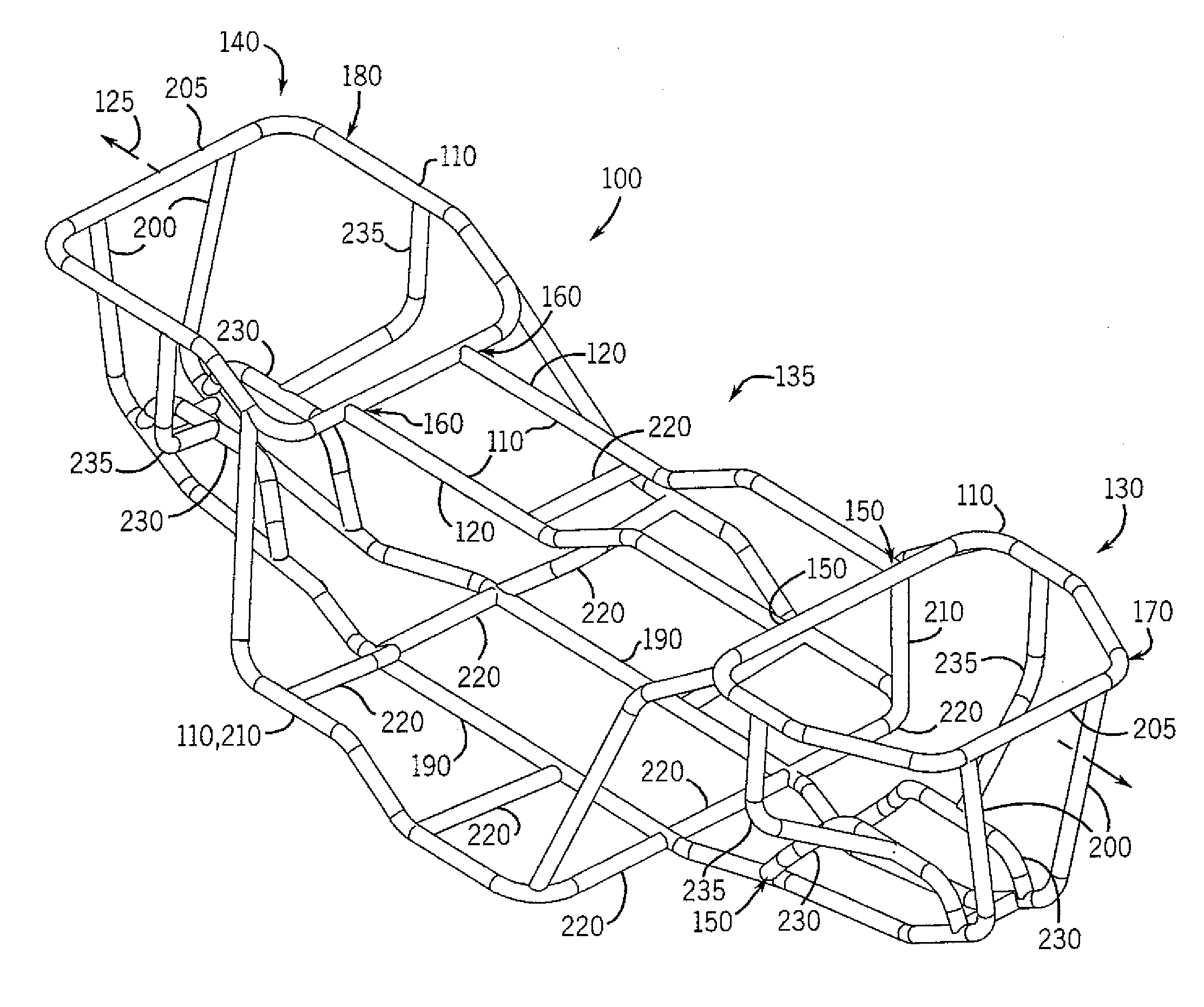
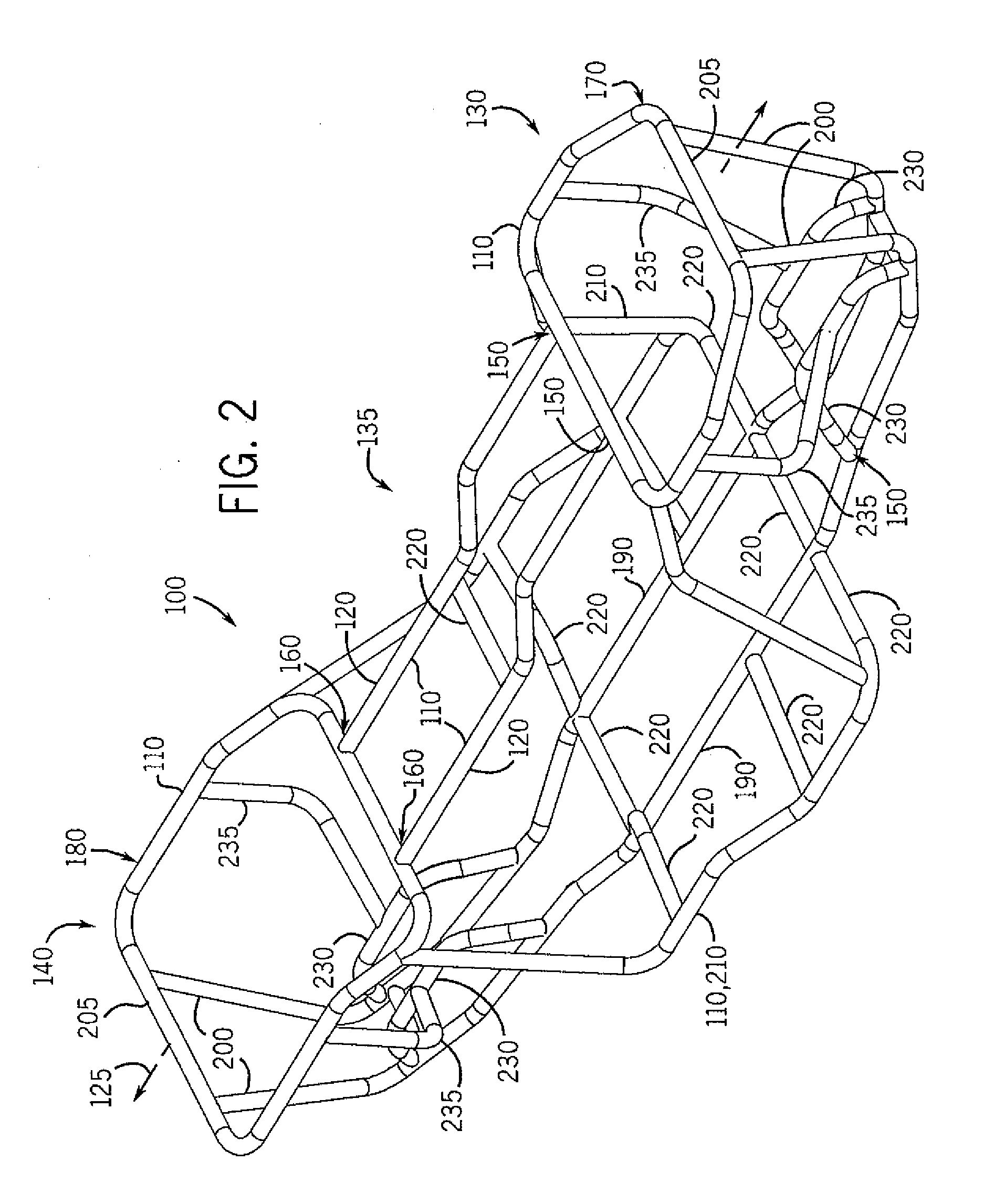
More particularly, while the frames of conventional reduced-size vehicles are satisfactorily designed for the purpose of carrying the operator and the various internal vehicle systems, such conventional frames have not been designed with the aim of effectively dissipating energy if the vehicles hit immovable objects such as trees, or with the aim of reducing the effects of side impacts upon the vehicles.
Further, because the struts / tubes, castings and stampings forming the frames of conventional reduced-size vehicles extend from the front ends to the rear ends of the vehicles in proximity to the central longitudinal axes of the vehicles, the frames are exposed to, and not particularly well-suited to resisting, extreme forces and torques that can be applied to the vehicles in certain accidents where the front ends of the vehicles tend to be twisted in directions contrary to those of the rear ends of the vehicles.
In general, conventional frames have not been designed in a manner intended to enhance the crashworthiness of the reduced-size vehicles.
Further, the cooling systems of conventional reduced-size vehicles also have a number of drawbacks.
With respect to conventional front-mounted cooling systems, for example, such systems are typically vulnerable to clogging in the off-road environment due to contact with mud, leaves, grass, snow, seeds, etc., and to the possibility of puncture from rocks & sticks.
To the extent that extra guards are utilized to prevent puncture, these can exacerbate clogging events.
Further, in such systems, the radiators exhaust heat into the mid-sections of the vehicles, which can undesirably heat up the seats and the surrounding bodywork and in some circumstances expose the vehicle operators (particularly the operators' legs) to undesirable heat.
Additionally, when one such vehicle closely follows behind another such vehicle, the following vehicle can undesirably ingest dirty air expelled by the leading vehicle.
As for conventional rear-mounted cooling systems, such systems are typically vulnerable to puncture and physical harm when the vehicles are driven in reverse.
Such systems also can constrain suspension design and decrease vehicle system flexibility.
To guarantee sufficient air flow, such systems often require large amounts of space within the vehicles to be dedicated to the communication of air for cooling and long coolant lines from the engine to the heat exchanger.
Second, the horizontal placement of the muffler maximizes the surface area by which heat is convectively transferred away from the muffler and onto the plastic fender that is commonly located above it, which can result in significant and possibly undesirable heating of the fender.
Although some reduced-size vehicles include heat shields above their mufflers and / or highly reflective foil insulators on the bottom sides of the plastic fenders, the fenders and surrounding body work of such vehicles often still can become undesirably hot.

Method used


Image

  • Frame design for reduced-size vehicle
  • Frame design for reduced-size vehicle
  • Frame design for reduced-size vehicle

Examples


Embodiment Construction

[0057] Referring to FIG. 1, a perspective view of an exemplary reduced-size vehicle in accordance with at least some embodiments of the present invention, namely, an exemplary all-terrain vehicle (ATV) 10, is shown. As illustrated, the ATV 10 has an exterior appearance that is similar to the appearances of conventional ATVs, e.g., the vehicle has four tires 20 (three of which are visible), a saddle-type seat 30, motorcycle-type handlebars 40 for steering the vehicle, and a largely box-like shape. The four tires 20 typically are balloon-type tires pressurized to up to 10 psi, albeit in other embodiments the tires need not be balloon tires or be pressurized to such degree, but rather could be other types of tires, for example, non-deflatable tires, or tires pressurized at other levels (or tires that included or operated in association with pumping devices such that the tires could be inflated or deflated to a variety of pressures).

[0058] Also, front and rear cargo racks / storage racks...


PUM

PropertyMeasurementUnit
volumeaaaaaaaaaa
densityaaaaaaaaaa
speedaaaaaaaaaa

Abstract

Various embodiments of reduced-size vehicles such as all-terrain vehicles (ATVs) and utility vehicles (UVs) are disclosed herein. In at least some embodiments, the vehicles include frames that are wider near the front and rear sections of the vehicles than within the mid-sections of the vehicles. This, in combination with the use of shock-absorbers that are substantially vertically oriented, allows for the opening-up of large interior cavities within the front and rear sections of the vehicles within which can be positioned large front and rear internal compartments that can provide storage / carrying capacity as well as added buoyancy for the vehicle, among other things. Also, in at least some embodiments, the vehicles can include special cooling and / or exhaust systems having components that are positioned substantially within the mid-sections of the vehicles, thus further increasing the amounts of space available for the cavities / compartments within the front and rear sections of the vehicles.

Description

CROSS-REFERENCE TO RELATED APPLICATIONS [0001] This application claims the benefit of U.S. provisional patent application No. 60 / 640,410 entitled “Improved Reduced-Size Vehicle” and filed on Dec. 30, 2004, which is hereby incorporated by reference herein.STATEMENT REGARDING FEDERALLY SPONSORED RESEARCH OR DEVELOPMENT [0002] - - FIELD OF THE INVENTION [0003] This invention relates to reduced-size vehicles, particularly all-terrain vehicles (“ATVs”) and various utility vehicles (“UVs”). BACKGROUND OF THE INVENTION [0004] Reduced-size vehicles such as ATVs and UVs are becoming increasingly popular in North America and the world. Historically, ATVs can trace their origins to motorcycles. The ATV began as a motorcycle with two rear wheels, called an All-Terrain Cycle (ATC) and then, due to safety considerations, evolved to include a second front wheel so as to become the conventional four-wheeled ATV. As ATVs have further evolved over the past twenty years, many other aspects of the vehi...

Claims


Application Information

Patent Timeline
Patent Type & Authority Applications(United States)
IPC IPC(8): B62D21/00B62D21/15B60J7/00
CPCY10T29/49622B60G2200/144B60G2206/10B60G7/001B62D21/183B62K5/01B60G3/06B62D29/043Y10T29/49826Y10S180/908B62D23/005B60G2200/142B60G2206/012B60G3/20B60G2202/24B60G2300/12B60G2202/12B60G11/15B62K19/46
Inventor DAVIS, ERIC A.DAVIS, BRIAN P.DAVIS, RICHARD A.
Owner AMERICAN OFF ROAD TECH
Why Eureka
Try Eureka