Diffraction grating, light-receiving element, and optical head and optical recording/reproducing apparatus utilizing them

a technology of light-emitting elements and optical heads, which is applied in the direction of data recording, instruments, other printing materials, etc., can solve the problems of inability to eliminate first-order diffracted beams having an unused wavelength completely, difficulty in providing optical heads in a small size, and inability to accurately detect signals

Inactive Publication Date: 2006-08-31
TDK CORPARATION
View PDF20 Cites 11 Cited by
  • Summary
  • Abstract
  • Description
  • Claims
  • Application Information

AI Technical Summary

Benefits of technology

[0029] The invention makes it possible to provide a diffraction grating and a light-receiving element allowing detection of a high quality signal and an optical head and an optical recording / reproducing apparatus utilizing them.

Problems solved by technology

It is therefore necessary to design the optical system of the optical head with a sufficiently long optical path length, which makes it difficult to provide the optical head in a small size.
Since the stray light enters a light-receiving element after being reflected by the optical recording medium, accurate signal detection is hindered.
However, when the ratio of the quantity of the 0-order beam diffracted to the quantity of the first-order beams diffracted is set high, a problem arises in that first-order diffracted beams having an unused wavelength cannot be eliminated completely.

Method used


Image

  • Diffraction grating, light-receiving element, and optical head and optical recording/reproducing apparatus utilizing them
  • Diffraction grating, light-receiving element, and optical head and optical recording/reproducing apparatus utilizing them
  • Diffraction grating, light-receiving element, and optical head and optical recording/reproducing apparatus utilizing them

Examples


first embodiment

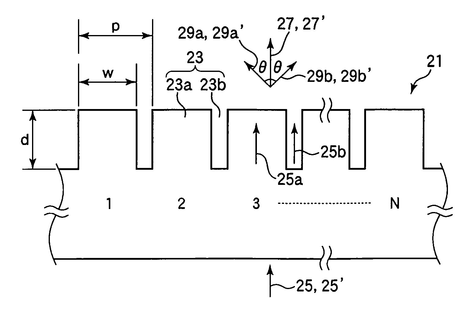
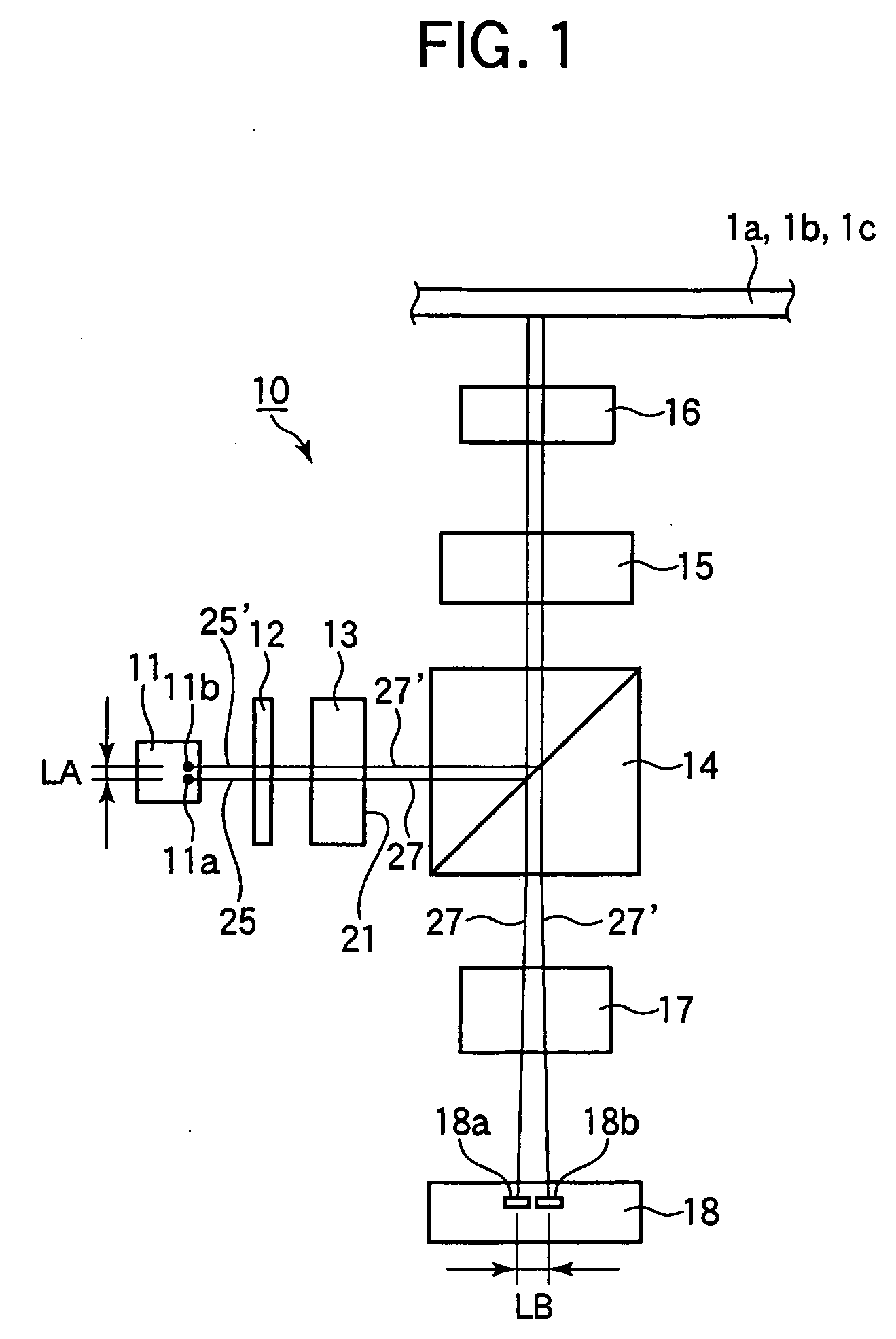
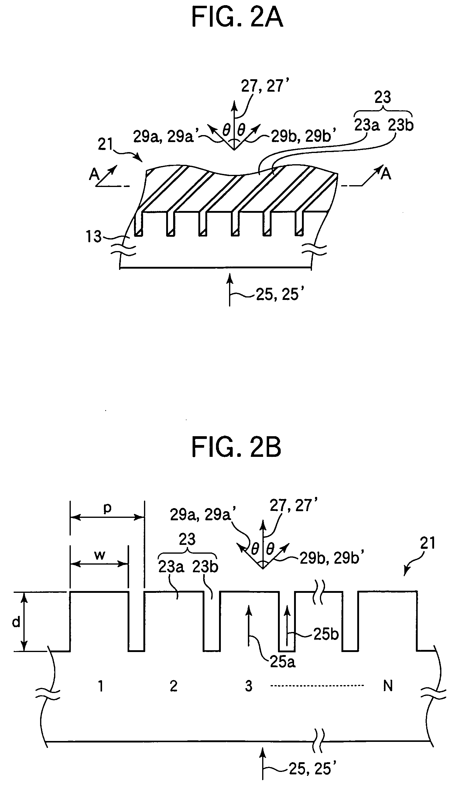
[0043] A description will now be made with reference to FIGS. 1 to 11 on a diffraction grating, a light-receiving element, and an optical head and an optical recording / reproducing apparatus utilizing them according to a first embodiment of the invention. In the present specification, a general term “diffracting grating” implies both of a diffracting element in the form of a straight grating and a diffracting element in the form of a curved grating. FIG. 1 shows a schematic configuration of an optical head 10 of the present embodiment. For example, the optical head 10 can be used for a first optical recording medium 1a, a second optical recording medium 1b (a DVD type optical recording medium), and a third optical recording medium 1c (a CD type optical recording medium). The optical head 10 includes a two-wavelength semiconductor laser (light source) 11, a phase difference plate 12, a phase modulation type diffraction grating 13, a beam splitter 14, a collimator lens 15, a rising mir...

second embodiment

[0120] A description will now be made with reference to FIGS. 12 and 13 on a diffraction grating, a light-receiving element, and an optical head and an optical recording / reproducing apparatus utilizing them according to a second embodiment of the invention. The diffraction grating 13 of the above-described embodiment has the diffracting region 21 which has a linear shape when viewed in a direction normal to the light entrance surface thereof. On the contrary, a diffraction grating 40 of the present embodiment is characterized in that it has a diffracting region 41 which has a wavy shape when viewed in a direction normal to a light entrance surface thereof. The configurations of the optical head and the optical recording / reproducing apparatus of the present embodiment will not be described because they are the same as those in the above-described embodiment. The method of detecting a tracking servo signal employed for the optical head of the present embodiment will not be described b...


PUM


Abstract

The invention relates to a diffraction grating, a light-receiving element, and an optical head and an optical recording / reproducing apparatus utilizing them and provides a diffraction grating and a light-receiving element capable of detecting a signal of high quality and an optical head and an optical recording / reproducing apparatus utilizing them. A diffraction grating includes a diffracting region which is formed only on a light exit surface and which diffracts and separates first laser light or second laser light emitted by a two-wavelength semiconductor laser to generate a main beam and positive and negative first order sub beams. The depth of concavity formed on the diffracting region is 220 nm. The irregularities are formed such that the pitch length thereof is 22 μm and such that a convexity thereof has a width of 17.6 μm. The ratio of the width of the convexity to the pitch length of the irregularities is 0.8.

Description

BACKGROUND OF THE INVENTION [0001] 1. Field of the Invention [0002] The present invention relates to a diffraction grating, a light-receiving element, and an optical head and an optical recording / reproducing apparatus utilizing them. [0003] 2. Description of the Related Art [0004] An optical recording / reproducing apparatus includes an optical head for recording information in predetermined regions of a plurality of tracks formed on, for example, a disk-shaped optical recording medium so as to extend along the circumferential direction of the optical recording medium and to repeat in the radial direction of the optical recording medium or reproducing information recorded in predetermined regions of the tracks. Optical heads include recording-only types which are used only for recording information on an optical recording medium, reproduction-only types which are used only for reproducing information, and recording / reproduction types which can be used for both of recording and reprodu...

Claims


Application Information

Patent Timeline
Patent Type & Authority Applications(United States)
IPC IPC(8): G02B5/18G02B27/44
CPCG02B5/1866G11B7/1275G11B7/1353G11B2007/0006B42D15/008G09B19/00
Inventor SHIBUYA, GIICHISATO, YOSHINORI
Owner TDK CORPARATION
Why Eureka
Try Eureka