Reflector for light source of projector

a projector and light source technology, applied in the direction of point-like light sources, incadescent envelopes/vessels, lighting and heating apparatus, etc., can solve the problems of low heat conductivity of glass, difficult fanning of glass parts, and heavy weight, and achieve the effect of not affecting the heat conductivity of aluminum metal or the like, and high power consumption

Inactive Publication Date: 2006-09-07
MUTSUKI ELECTRIC
View PDF7 Cites 3 Cited by
  • Summary
  • Abstract
  • Description
  • Claims
  • Application Information

AI Technical Summary

Benefits of technology

[0010] The invention-wise reflector comprises: a cup-shaped part that is formed by forging or casting from aluminum metal or alloy or the like metal, inner face of the cup-shaped part being mirror finished; and a barrel portion disposed at center of the cup-shaped part and configured to receive an electric-discharge lamp

Problems solved by technology

The projectors widely used before are formed of cathode-ray tubes and thus are bulky and weighty.
When to increase brightness of the screen, electric power on the lamp has to be increased; and thus, heat generation is increased as to thereby cause trouble at reflective film disposed on inner side of the reflector as well as the electric-discharge lamp that is attached to the lamp reflector.
Moreover, tolerable temperature of the lamp reflector is about 1200° C. while temperature around the lamp may become as high as 1000° C. Thus, the cooling by a fan is a must when to cope with such high temperature accompanied with increasing of the luminescence; and it is a biggest problem how to lead out, by conduction, heat at inner-center space of the reflector, at which the lamp is located.
Glass has low heat conductivity, and thus glass part is hard to be cooled by fanning.
Thus, generated heat would not be escaped from inside of the reflector and might cause problems such as rupture of the lamp bulb or tube, which will cause spattering of mercury, due to excessive rising of its temperature; as to hamper enhancing of the luminescence.
Such co

Method used


Image

  • Reflector for light source of projector
  • Reflector for light source of projector
  • Reflector for light source of projector

Examples


Embodiment Construction

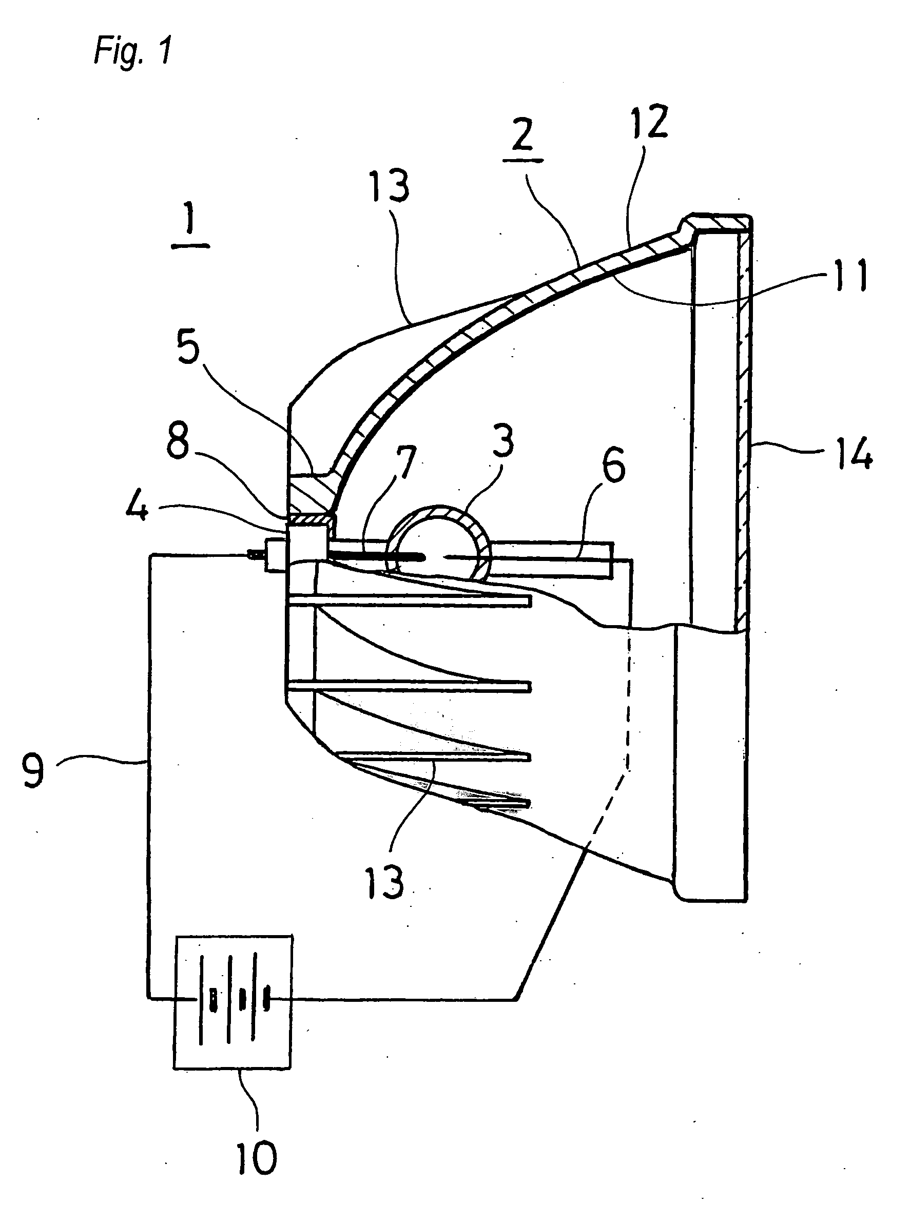
[0015] An embodiment of the invention-wise reflector for a light source of projector will be explained in conjunction with the drawings, for a case the reflector is used for a projector formed of an LCD device. FIG. 1 shows a projection light source 1 which is for the LCD projector and is formed of a cup-shaped reflector 2 and an electric-discharge lamp 3.

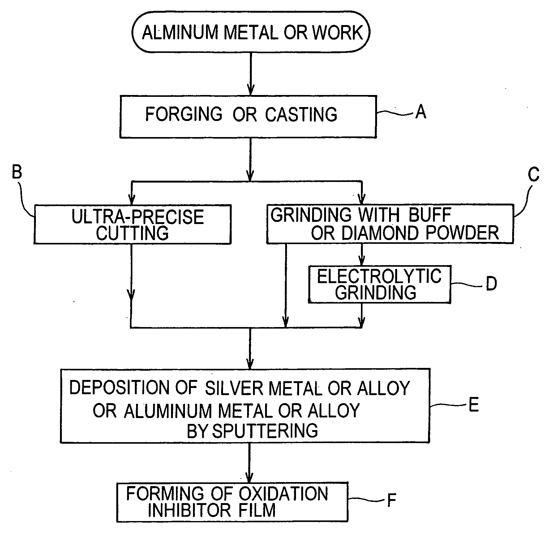
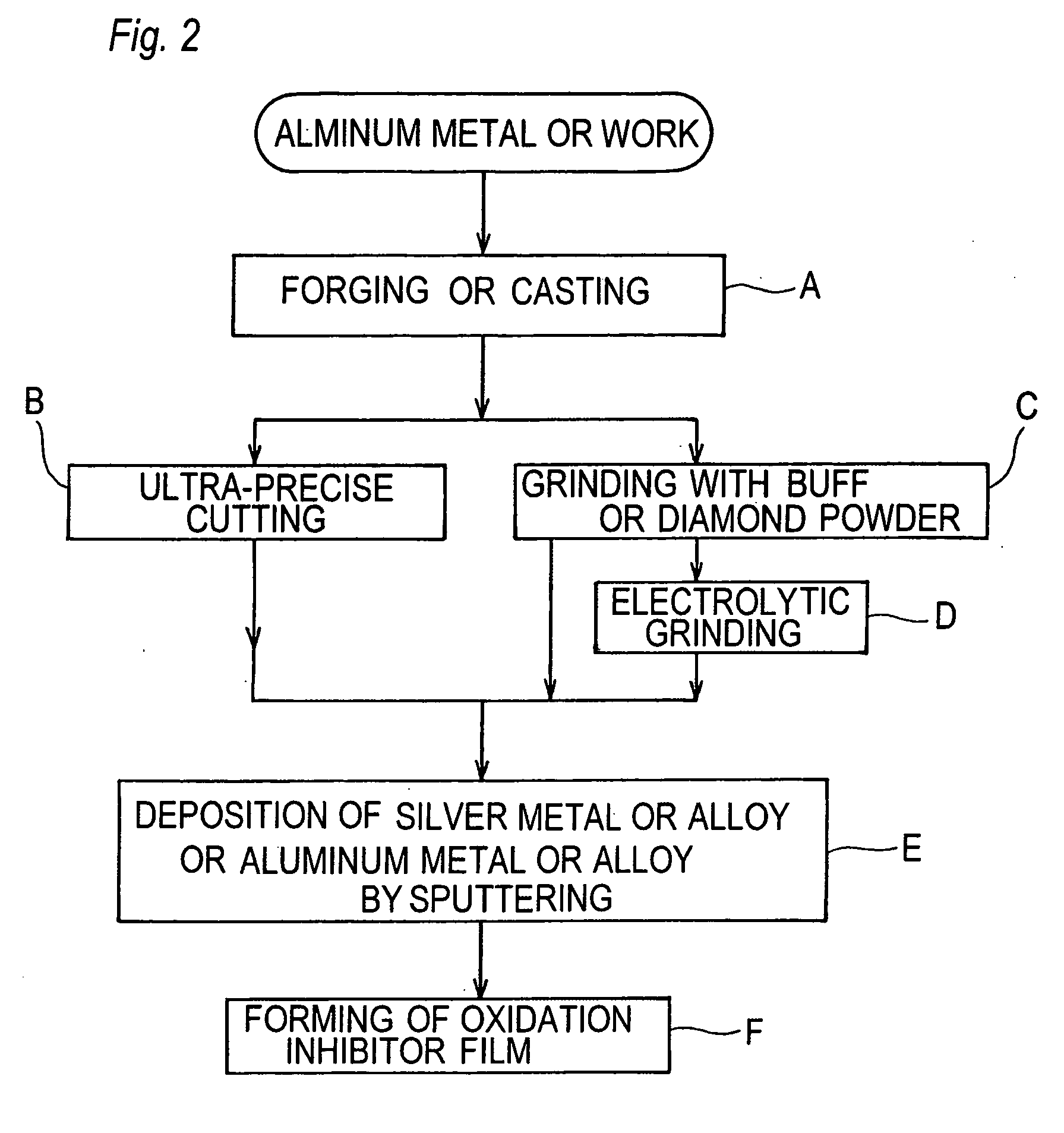
[0016] The reflector 2 is formed of a metal of good heat conductivity such as aluminum, and is shaped in a cup shape with thickness in a range of 2 through 3 mm by forging or casting. At a center of bottom of the cup shape, the reflector 2 has a barrel portion 5 that receives the base 4 of the electric-discharge lamp 3. In respect of forming method, the forging is preferred to the casting because the forged one has higher metallographic density and is easy to achieve surface finishing by cutting operation as to provide higher quality.

[0017] On ends of the lamp tube 3, cathode 6 and anode 7 is respectively formed as sealed off fro...


PUM

PropertyMeasurementUnit
Electrical conductivityaaaaaaaaaa
Luminanceaaaaaaaaaa

Abstract

A reflector for light source of a projector, comprises a cup-shaped part that is formed by forging or casting from aluminum metal or alloy or the like metal, inner face of the cup-shaped part being mirror finished by ultra-precise cutting technique or by grinding with buff or diamond powder as not to have grooves or distortion; and a barrel portion disposed at center of the cup-shaped part and configured to receive an electric-discharge lamp. Omitted thereby is a coating of silicone-based resin that is a must for a reflector formed by metal spinning technique as to cover up the grooves and distortion. Thus, good heat conductivity of the aluminum metal or the like is not hampered, as to achieve a reflector for high-luminance lamp with high power consumption.

Description

TECHNICAL FIELD [0001] This invention relates to a reflector for an electric-discharge lamp that is used as a light source for a projector formed of a liquid-crystal display (LCD) or a digital light processing (DLP) device or the like. BACKGROUND ART [0002] The projectors widely used before are formed of cathode-ray tubes and thus are bulky and weighty. Recently, however, the projectors formed of the LCD or DLP devices having smaller dimensions and weight have become widespread. The projector has a lens for enlarging and projecting an image formed on the LCD device for example, as to achieve a displaying on a large screen. Such projector has an electric-discharge lamp (tube or bulb) of high luminescence as to facilitate excellent visibility even in a bright room. When to increase brightness of the screen, electric power on the lamp has to be increased; and thus, heat generation is increased as to thereby cause trouble at reflective film disposed on inner side of the reflector as wel...

Claims


Application Information

Patent Timeline
IPC IPC(8): H01K1/26H01K1/30H01J61/40H01J5/16F21Y101/00
CPCF21V7/22F21V29/505G02B5/10F21V7/24F21V7/28
Inventor MUTSUKI, KUNITOSHISHIMIZU, YOHEI
Owner MUTSUKI ELECTRIC
Why Eureka
Try Eureka