

Thin display device and plasma display
a thin display device and plasma display technology, applied in the direction of identification means, electrical apparatus casings/cabinets/drawers, instruments, etc., can solve the problems of an electro-magnetic wave noise that is apparent, becomes an extremely expensive flexible cable, etc., and achieves the effect of effectively restraining an electro-magnetic wave noise and simple and inexpensive configuration
- Summary
- Abstract
- Description
- Claims
- Application Information
AI Technical Summary
Benefits of technology
Problems solved by technology
Method used
Image

Examples
first embodiment
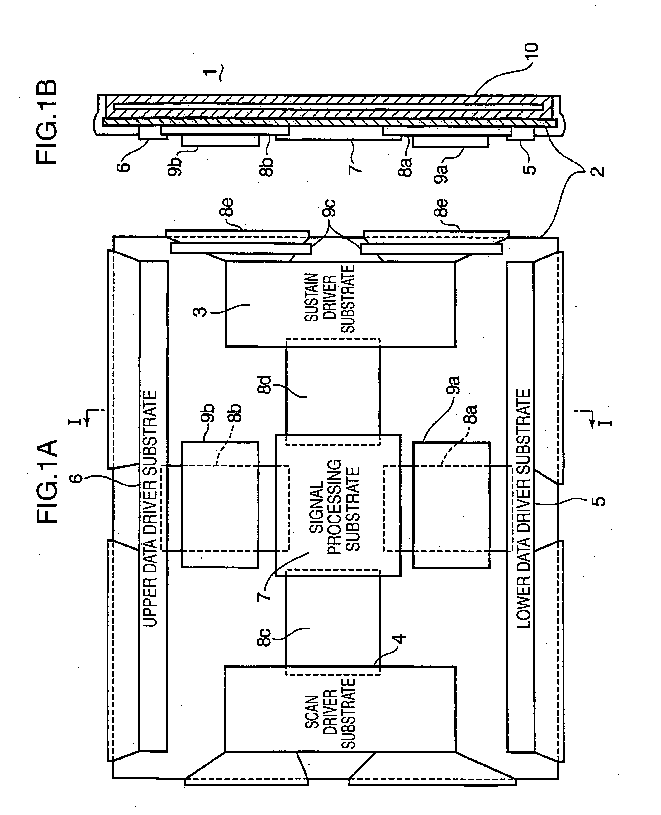
[0030] As shown in FIGS. 1A and 1B, in a plasma display 1 according to a first embodiment of the present invention, an aluminum chassis 2 is attached to the rear side of a PDP 10. This aluminum chassis 2 is formed by an aluminum die-casting. To this aluminum chassis 2, a plurality of substrates are each attached at a predetermined position, such as a sustain driver substrate 3, a scan driver substrate 4, a lower data driver substrate 5, an upper data driver substrate 6 and a signal processing substrate 7. The signal processing substrate 7 is located substantially in the middle of the aluminum chassis 2. Below this signal processing substrate 7, the lower data driver substrate 5 is placed, and the upper data driver substrate 6 is located above it. In FIG. 1A, the sustain driver substrate 3 and the scan driver substrate 4 are disposed on the right side and the left side of the signal processing substrate 7, respectively.
[0031] The above described substrates 3, 4, are connected electr...
second embodiment
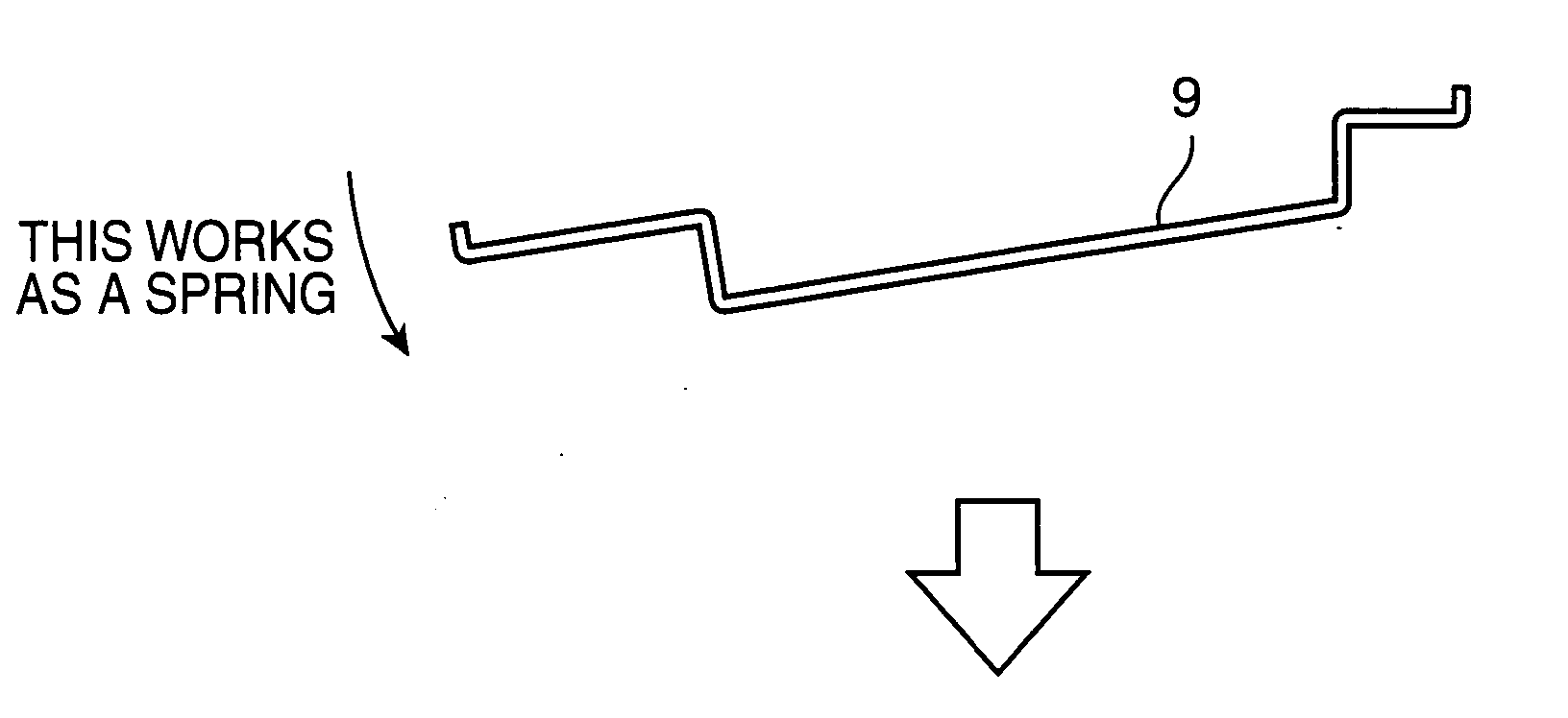
[0047] In the above described first embodiment, the pressing plates 9a, 9b are connected to the flexible cables 8a, 8b, at two places in their length directions. However, in this second embodiment, as shown in FIGS. 6A and 6B, such a connection is made at one place in the length directions of a flexible cable 8. In this case, a pressing plate 9 may also be wider than the flexible cable 8, so that this pressing plate 9 can be connected to both sides of the flexible cable 8. As shown in the figure, a boss 47 with a screw hole 48 is pushed into the aluminum chassis 2. Then, a screw 50 for fixing the pressing plate 9 is fitted into this boss 47. Thereby, the pressing plate 9 is fixed on the aluminum chassis 2.
[0048] As shown in FIG. 6A, in the case of the pressing plate 9 works as a spring, using its biasing force, it can press the flexible cable 8 more effectively. This pressing plate 9 may also be a metal plate, as long as it functions as a leaf spring. Besides, it may also be a non-...
third embodiment
[0052] A plasma display according to a third embodiment of the present invention will be described with reference to FIGS. 7A and 7B. In those figures, the aluminum chassis 2 and the flexible cable 8 are the same as those of the first embodiment. Herein, the parts which are different from those of the first embodiment are described. Hence, the same reference numerals are given to the same configurations as those of the first embodiment, and thus, their description is omitted.
[0053] In this third embodiment, a pressing plate 12 is electrically connected to the aluminum chassis 2. The pressing plate 12 is, for example, an aluminum plate. Besides, a boss 13 with a screw hole 16 is buried into the aluminum chassis 2. Then, into this screw hole 16 of the boss 13, a conductive screw 14 is fitted which is inserted through a screw insertion hole 18 of the pressing plate 12. As this screw 14, for example, a steel material can be used which is subjected to metallic plating (e.g., nickel plat...
PUM
 Abstract
Description
Claims
Application Information