Optical transparent member and optical system using the same

a technology of optical system and optical member, applied in the field of optical transparent member, can solve the problems of difficult control of pitch and height, requiring a very high capital expenditure, and reducing light transmittance, and achieve the effect of high-performance anti-reflection

Inactive Publication Date: 2006-09-07
CANON KK +1
View PDF10 Cites 90 Cited by
  • Summary
  • Abstract
  • Description
  • Claims
  • Application Information

AI Technical Summary

Benefits of technology

[0011] The present invention has been made in view of the related art described above, and its object is to provide an optical transparent member which can maintain a high-performance antireflection effect over a long period of time for any base, and an optical system using the same.

Problems solved by technology

However, in a technique using fine particles, it is difficult to control the pitch and height of the finely periodic structure, and if a height for obtaining a sufficient antireflection effect is to be obtained, the pitch increases to cause scattering, and conversely, the light transmittance decreases.
The method of forming fine patterns by the finely processing apparatus has a disadvantage that not only such a method of forming a pattern require very large scale equipment, thus requiring a very high capital expenditure, but also although the method is suitable for formation of a pattern on a flat surface, it is very difficult to form a pattern on a complicated shape such as a curved surface.
In addition, the method is unsuitable for application to general-purpose optical elements because throughput is low and processing on a large area is difficult.
Consequently, when alkali ions and the like of the base are migrated to the surface and the surface is brought into an alkali atmosphere due to an exchange reaction with water in air, maintenance of a shape of irregularities becomes difficult due to decomposition of the surface and thus the performance is degraded.
For a base having a refractive index significantly different from that of alumina, a difference in refractive index at an interface between the base and alumina is so large that the antireflection performance is not sufficiently exhibited.

Method used


Image

  • Optical transparent member and optical system using the same
  • Optical transparent member and optical system using the same
  • Optical transparent member and optical system using the same

Examples


example 1

[0081] A clear float glass substrate (composition: soda lime silicate type, refractive index ng=1.52) having a size of about 100 mm×100 mm and a thickness of about 2 mm was ultrasonically washed with isopropyl alcohol, dried, and then used as a glass substrate for coating.

[0082] Tetraethoxy silane (TEOS) was dissolved in ethanol (EtOH), a 0.01 M aqueous phosphoric acid solution was added to the resultant solution as a catalyst, and then the resultant mixture was stirred for 6 hours. The molar ratio of the components at this time is TEOS:EtOH:H3PO4 aq=1:40:2. Titanium n-butoxide (TBOT) was dissolved in ethanol, ethyl acetoacetate (EAcAc) was then added to the resultant solution as a stabilizer, and the resultant mixture was stirred at room temperature for 3 hours. The molar ratio of the components is TBOT:EtOH:EAcAc=1:20:1. A TiO2 sol solution was added to'the aforementioned SiO2 sol solution so that a molar ratio of SiO2:TiO2=95:5 was obtained, and the resultant mixture was stirred...

example 2

[0088] An S-TIH53 glass substrate (manufactured by OHARA INC., refractive index n=1.84) having a size of about 50 mm×50 mm and a thickness of about 1 mm was ultrasonically washed with isopropyl alcohol, dried, and then used as a glass substrate for coating.

[0089] A TiO2 sol solution was added to the aforementioned SiO2 sol solution so that a molar ratio of SiO2:TiO2=7:3 was obtained, and the resultant mixture was stirred at room temperature for 2 hours, and then used as a SiO2—TiO2 coating solution as in Example 1. Then, the aforementioned coating glass substrate was immersed in this coating solution, a coating film was formed on the surface of the glass substrate by the dipping method (at a lifting speed of 0.5 mm / second, and at 20° C. and 56% R.H.). The glass substrate was dried, and then thermally treated by baking at 400° C. for an hour, and a transparent amorphous SiO2 / TiO2 film was coated thereon. The thickness and the refractive index of the obtained film were measured, and ...

example 3

[0094] An S-TIH53 substrate (manufactured by OHARA INC., refractive index nb=1.84) same as that in Example 2 was used as a glass substrate for coating.

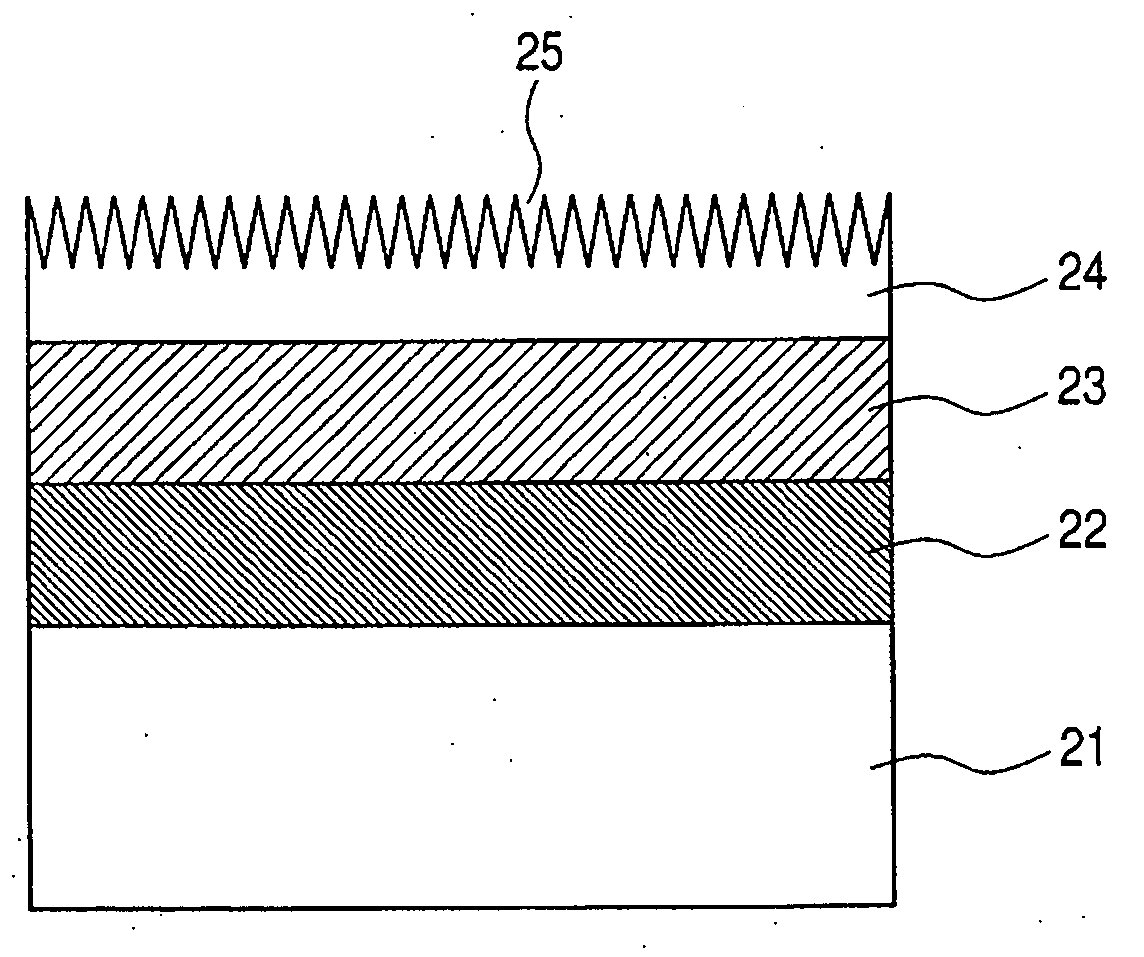
[0095] SiO2 / TiO2 (7 / 3) was coated, and then a transparent amorphous SiO2 / TiO2 film was formed in the same manner as in Example 2. The thickness and the refractive index of the obtained film were measured, and the result of the measurement showed that the thickness was 28 nm and the refractive index was na=1.67.

[0096] Aluminum-sec-butoxide [Al(O-sec-Bu)3] was dissolved in 2-propanol [IPA], ethyl acetoacetate [EAcAc] was added to the resultant solution as a stabilizer, and the resultant mixture was stirred at room temperature for about 3 hours to prepare an Al2O3 sol solution. Here, the molar ratio of the solution was Al(O-sec-Bu)3:IPA:EAcAc=1:20:1. Titanium-n-butoxide [Ti(O-n-Bu)4] was also dissolved in IPA, EAcAc was added to the resultant solution, and the resultant mixture was stirred for about 3 hours to prepare a TiO2-sol soluti...


PUM

PropertyMeasurementUnit
thicknessaaaaaaaaaa
thicknessaaaaaaaaaa
roughnessaaaaaaaaaa

Abstract

It is an object to provide an optical transparent member capable of maintaining a high-performance antireflection effect for a base over a long period of time, and an optical system using the same, specifically an optical transparent member including on a base a layer containing SiO2 as a main component, a layer containing Al2O3 as a main component, and a plate crystal layer formed from plate crystals containing Al2O3 as a main component, wherein the surface of the plate crystal layer has a shape of irregularities, and an optical system using the same.

Description

BACKGROUND OF THE INVENTION [0001] 1. Field of the Invention [0002] The present invention relates to an optical transparent member having an antireflection performance and an optical system using the same, and more particularly to an optical transparent member suitable for obtaining a high antireflection performance from a visible region to a near infrared region over a long period of time, and an optical system using the same. [0003] Particularly, the optical transparent member of the present invention can adapt to a transparent base having any refractive index, shows an excellent antireflection effect to visible light, and has a long-term weathering resistance, and therefore it can be used for optical members of various kinds of displays of word processors, computers, televisions, plasma display panels and the like; polarizing plates of liquid crystal apparatuses; sunglass lenses, graduated eyeglass lenses, finder lenses for cameras, prisms, fly-eye lenses, toric lenses, and vario...

Claims


Application Information

Patent Timeline
Patent Type & Authority Applications(United States)
IPC IPC(8): B32B13/04B32B9/00B32B19/00G02B1/11B32B3/30G02B1/111
CPCC03C1/006C03C17/3417C03C2217/425C03C2217/465C03C2217/73C03C2217/77G02B1/11G02B1/118G02B1/02
Inventor YAMADA, MASAYUKIKOTANI, YOSHINORITANAKA, HIROYUKIOKUNO, TAKEHARUMINAMI, TSUTOMUTATSUMISAGO, MASAHIROTADANAGA, KIYOHARU
Owner CANON KK
Why Eureka
Try Eureka