
Cooling device for electronic component using thermo-electric conversion material

Inactive Publication Date: 2006-09-14
MURORAN INSTITUTE OF TECHNOLOGY +1
View PDF5 Cites 73 Cited by
  • Summary
  • Abstract
  • Description
  • Claims
  • Application Information

AI Technical Summary

Benefits of technology

[0012] According to Patent Documents 2 to 6, electric power generated from heat by a thermoelectric conversion element including both n-type and p-type materials is supplied to an external load such as an external charger, a fan, and a piezoelectric vibrator to aid cooling. It may be pointed out that the generation of electric power removes heat to result in a decrease in temperature. The connection of an external load (resistor), however, increases the overall resistance of the circuit, and thus decreases current flowing through the circuit. In addition, the use of an external load is insufficient because part of electric power consumed by the external load is inevitably converted to heat again. According to Patent Document 2, external power supply is required for cooling. According to Patent Documents 4 to 6, an electronic component such as a control circuit is required together with power supply therefor.
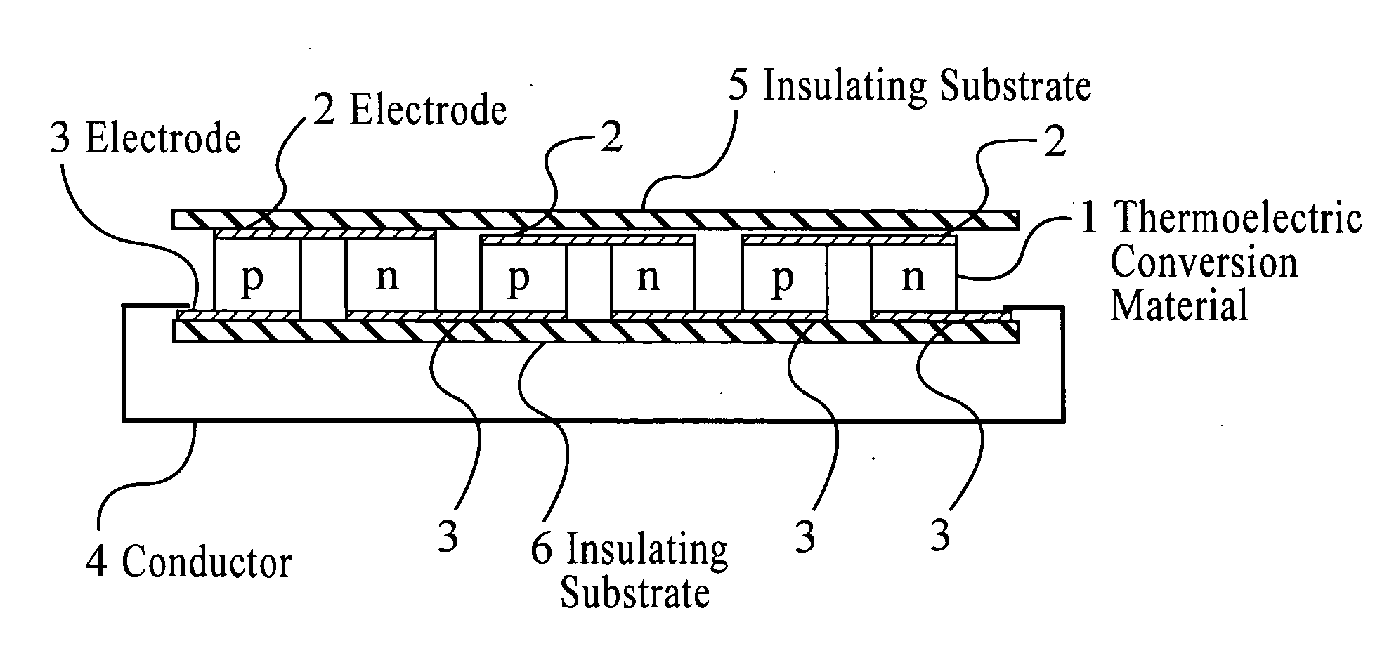
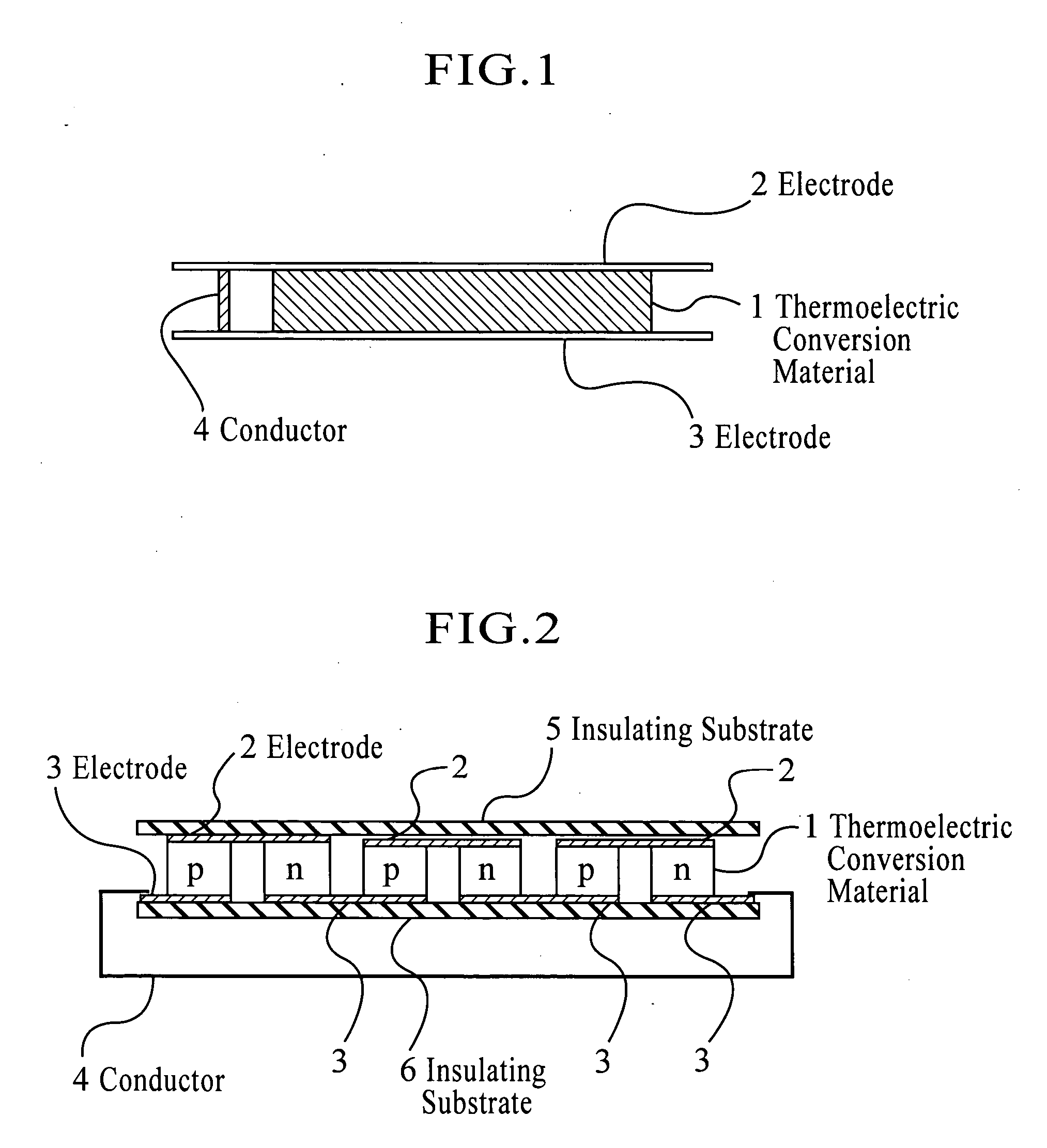
[0018] The cooling device according to the present invention may be attached to a part of an electronic component where its temperature rises. The temperature of one electrode side of the cooling device in contact with the component rises as the temperature of the component rises. On the other hand, the other electrode side in contact with the thermoelectric conversion material shows no significant temperature rise because the electrode side is exposed to a refrigerant such as outside air and water. Accordingly, a temperature difference occurs spontaneously between the two sides of the cooling device. This temperature difference allows current to flow through the cooling device and cool the high-temperature side in contact with the cooling device.
[0028] The above formulas show that a larger amount of current produces a larger cooling effect. Hence, the connection of an external load is disadvantageous in view of cooling a heat-generating device because the external load increases the overall resistance of the circuit. If the top and bottom electrodes 2 and 3 of the cooling device are connected to an external load, rather than are short-circuited, the external load consumes the resultant current to dissipate heat removed by the cooling device to the outside through the electrical circuit. In this case, however, the external load decreases the amount of current, and thus lowers the cooling effect.

Problems solved by technology

Such a fin-shaped radiation plate alone, however, lacks the ability to dissipate heat effectively.
This element has a complicated structure and involves high production cost because both p-type and n-type materials must be prepared and combined.
In addition, this element requires external current supply, and thus involves operating cost.
The need for combining such a component, however, complicates the structure of the devices.
It may be pointed out that the generation of electric power removes heat to result in a decrease in temperature.
The connection of an external load (resistor), however, increases the overall resistance of the circuit, and thus decreases current flowing through the circuit.
In addition, the use of an external load is insufficient because part of electric power consumed by the external load is inevitably converted to heat again.

Method used


Image

  • Cooling device for electronic component using thermo-electric conversion material
  • Cooling device for electronic component using thermo-electric conversion material

Examples


example 1

[0043] A radiation plate having the structure shown in FIG. 1 was produced by providing a BiTe-based p-type thermoelectric conversion material (4 mm long by 10 mm wide by 4 mm thick) between electrodes made of copper foil (40 μm thick) and soldering the surfaces of the thermoelectric conversion material and the copper foil.

[0044] A surface of the radiation plate was brought into contact with a surface of a planar heater, as a heat-generating device requiring cooling. A Peltier element was provided on the opposite surface of the radiation plate to cool the surface and increase the temperature difference between the high-temperature side and the low-temperature side.

[0045] While the Peltier element was supplied with current to cool the radiation plate, the heater was supplied with an AC voltage of 50 V. According to measurement with a chromel-alumel thermocouple, the temperature of the junction between the heater and the radiation plate was 62.5° C.

example 2

[0049] The BiTe-based p-type thermoelectric conversion material was replaced with a BiTe-based n-type thermoelectric conversion material. According to temperature measurement performed under the same conditions as in Example 1, the temperature in the case where the two electrodes, which functioned as a cathode and an anode, were changed from an open-circuit state to a short-circuit state was 66.5° C., and the temperature in the case where the electrodes were not short-circuited was 67.7° C. These results show a temperature drop of 1.2° C.

example 3

[0050] As a radiation plate having the structure shown in FIG. 2, PV2-S, manufactured by Eco 21, Inc., was used with its terminals short-circuited. A surface of the radiation plate was brought into contact with a surface of a planar heater, as a heat-generating device requiring cooling. No component was provided on the opposite surface of the radiation plate to cool it naturally by outside air. The heater was supplied with an AC voltage of 90 V. According to measurement with a chromel-alumel thermocouple, the temperature of the junction between the heater and the radiation plate was 99° C.


PUM


Abstract

A cooling device for a heat-generating electronic component such as a semiconductor integrated circuit element is provided. In particular, a cooling device using a thermoelectric conversion material is provided. A cooling device for an electronic component includes a thermoelectric conversion material disposed between two electrodes that function as a cathode and an anode and are electrically short-circuited. The thermoelectric conversion material is either a p-type material or an n-type material or a combination of p-type and n-type materials arranged alternately in series. This cooling device is brought into contact with an electronic component requiring cooling so that one electrode side in contact with the thermoelectric conversion material becomes a low-temperature side and the other electrode side becomes a high-temperature side. A temperature difference between the two electrodes causes the thermoelectric conversion material to produce a thermoelectromotive force which generates current to cool the high-temperature side.

Description

TECHNICAL FIELD [0001] The present invention relates to cooling devices for heat-generating electronic components such as semiconductor integrated circuit elements, and particularly to a cooling device using a thermoelectric conversion material. BACKGROUND ART [0002] A CPU in a PC, for example, is equipped with an aluminum fin-shaped radiation plate to inhibit a rise in temperature of the CPU by heat generation or, in some cases, is forced to cool by supplying current to a Peltier element from an external power supply (for example, Patent Documents 1 and 2). In addition, some known devices provide a larger cooling effect using an electromotive force produced by the Seebeck effect of a thermoelectric conversion material (for example, Patent Documents 3 to 6). [0003] Patent Document 1: Japanese Unexamined Patent Application Publication No. 9-139525 [0004] Patent Document 2: Japanese Unexamined Patent Application Publication No. 2002-50727 [0005] Patent Document 3: Japanese Examined Ut...

Claims


Application Information

Patent Timeline
IPC IPC(8): F25B21/02H01L35/28F25D23/12H01L23/38H01L35/32H01L35/16
CPCH01L23/38H01L35/32H01L2924/0002H01L2924/00H10N10/17
Inventor HIRAI, SHINJINISHIMURA, TOSHIYUKIUEMURA, YOICHIROMORITA, SHIGENORIIGARASHI, KAZUMASA
Owner MURORAN INSTITUTE OF TECHNOLOGY
Learn More