Vehicle mounted stereo camera apparatus

a stereo camera and camera body technology, applied in the field of stereo camera equipment and stereo image process technique, can solve the problems of inability to absorb the influence caused by noise, inability to be denied, pixel misalignment, etc., and achieve the effect of high reliability, high accuracy and small siz

Inactive Publication Date: 2006-09-14
HITACHI LTD
View PDF5 Cites 34 Cited by
  • Summary
  • Abstract
  • Description
  • Claims
  • Application Information

AI Technical Summary

Benefits of technology

[0020] Also in JP-A-8-331548, it is possible to eliminate the phase difference between a sync signal used in one imaging unit and a video signal output by the imaging unit. However, when a plurality of such imaging units are provided, it cannot be guaranteed that no pixel alignment as shown in FIG. 12 occurs among data of images respectively output from the imaging units.
[0024] Another object of the present invention is to provide a vehicle mounted stereo camera apparatus in which a stereo image process can be performed by an image processing LSI using image data output by one imaging unit and image data output by another imaging unit so as to prevent occurrence of pixel misalignment between the image data.
[0025] A further object of the present invention is to provide a vehicle mounted stereo camera apparatus which can be made small in size as a whole, low in price and high in reliability without any misalignment even among the imaging timings of a plurality of imaging units.
[0028] the image data input into the image processing unit are synchronized with clock signals for importing and processing the image data respectively, so as to perform the stereo image process operation while eliminating horizontal pixel misalignment from the image data from the plurality of imaging units.
[0034] According to the present invention, a lag of timing (horizontal pixel misalignment) which may be generated when data of a plurality of taken images are propagated to the image processing LSI can be eliminated so that a stereo camera apparatus high in reliability and high in accuracy can be obtained.
[0035] In addition, it is not necessary to take it into consideration to set equal-length wiring as to lines between the respective imaging units and the image processing LSI. Accordingly, the system can be constructed with a minimum configuration, and the apparatus can be made small in size and low in price.

Problems solved by technology

It is therefore impossible to absorb the influence caused by noise or a temperature difference in real time after each unit has been mounted on the board.
In addition, it cannot be denied that it is likely that pixel misalignment as shown in FIG. 12 occurs among data of images output by a plurality of imaging units.
However, when a plurality of such imaging units are provided, it cannot be guaranteed that no pixel alignment as shown in FIG. 12 occurs among data of images respectively output from the imaging units.
However, even according to this method, it is difficult to design a board so as to dispose the external trigger signal generating unit 407 or the clock signal generating unit 408, for example, closely to both the first imaging unit 401 and the second imaging unit 402 when there is a long distance between the two imaging units.
It is therefore impossible to solve the aforementioned problem as to the imaging timing with accuracy required in a vehicle mounted environment.
In addition, due to the restriction placed on dispositions in a board, the degree of freedom in design is spoiled.
It is therefore difficult to attain the requirements while making the system smaller in size and lower in price.

Method used


Image

  • Vehicle mounted stereo camera apparatus
  • Vehicle mounted stereo camera apparatus
  • Vehicle mounted stereo camera apparatus

Examples


first embodiment

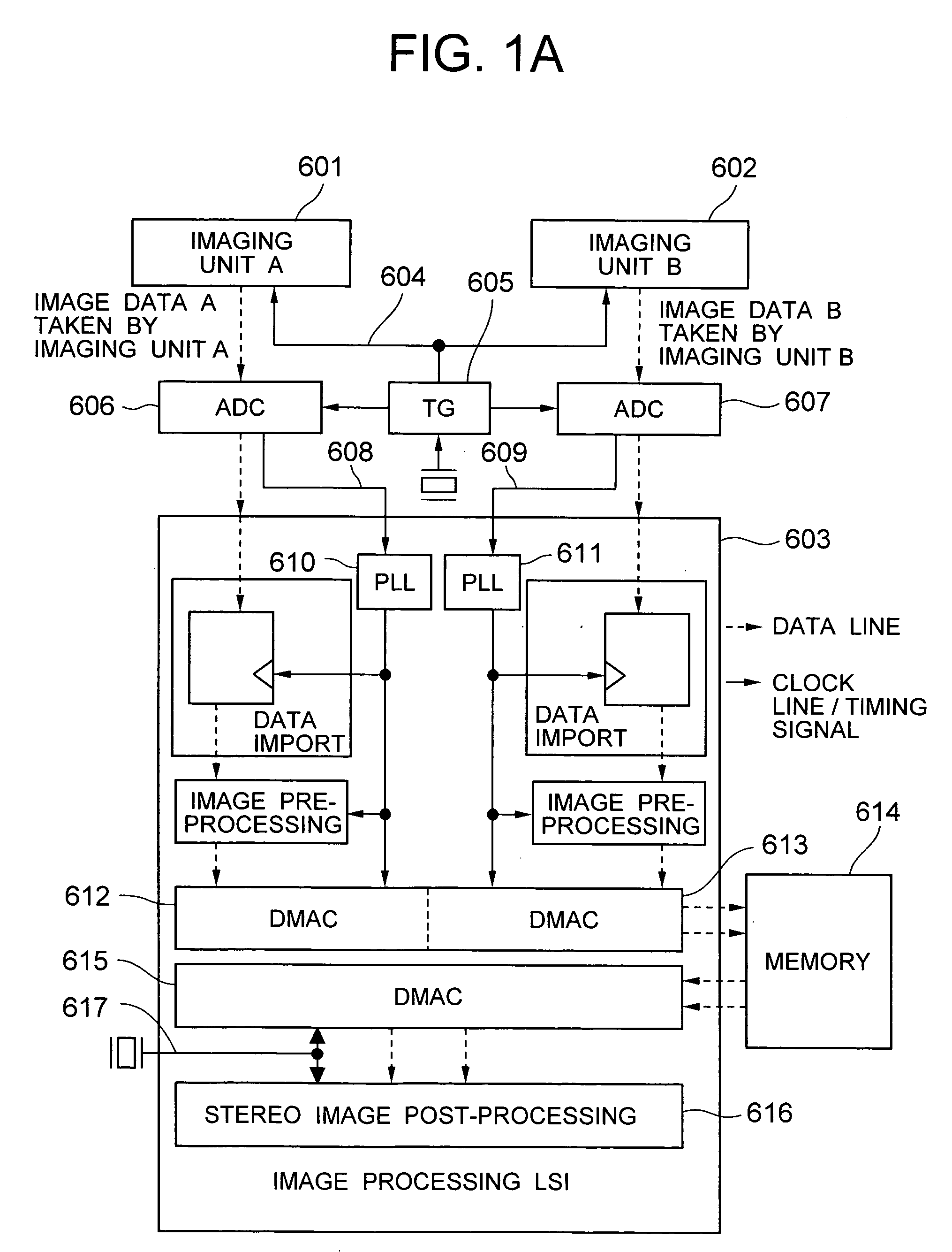
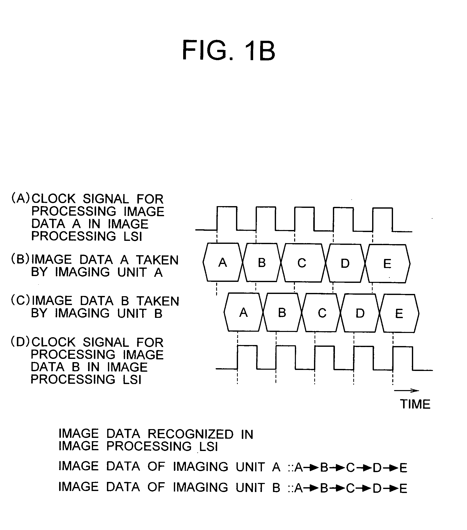
[0053] A vehicle mounted stereo camera apparatus according to a first embodiment of the present invention will be described below with reference to FIGS. 1A-1B and 2. FIG. 1A is a block diagram showing a configuration of the vehicle mounted stereo camera apparatus according to the first embodiment of the present invention. FIG. 1B is a timing chart showing a signal waveform in each unit of the vehicle mounted stereo camera apparatus shown in FIG. 1A. FIG. 2 is a chart showing an operation flow of a stereo image process in the vehicle mounted stereo camera apparatus according to the first embodiment.

[0054] In FIG. 1A, the stereo camera apparatus has a plurality of imaging units including an imaging unit A 601 and an imaging unit B 602, and one image processing LSI 603. Each imaging unit 601, 602 is connected to the image processing LSI 603 through a timing generator (TG) 605 for outputting an imaging timing signal 604 and an analog-to-digital (AD) converter (ADC) 606, 607.

[0055] Th...

second embodiment

[0068] A vehicle mounted stereo camera apparatus according to a second embodiment of the present invention will be described below with reference to FIGS. 3 to 7. FIG. 3 is a block diagram showing a configuration of the vehicle mounted stereo camera apparatus according to the second embodiment of the present invention. FIG. 4 is a diagram showing a specific configuration of an imaging timing misalignment detection mechanism in the vehicle mounted stereo camera apparatus according to the second embodiment. FIG. 5 is a chart showing operation timing at a normal time when there is no imaging timing misalignment in the imaging timing misalignment detection mechanism according to the second embodiment. FIG. 6 is a chart showing operation timing when imaging timing misalignment corresponding to half a clock period has been detected in the imaging timing misalignment detection mechanism according to the second embodiment. FIG. 7 is a chart showing operation timing when imaging timing misal...

third embodiment

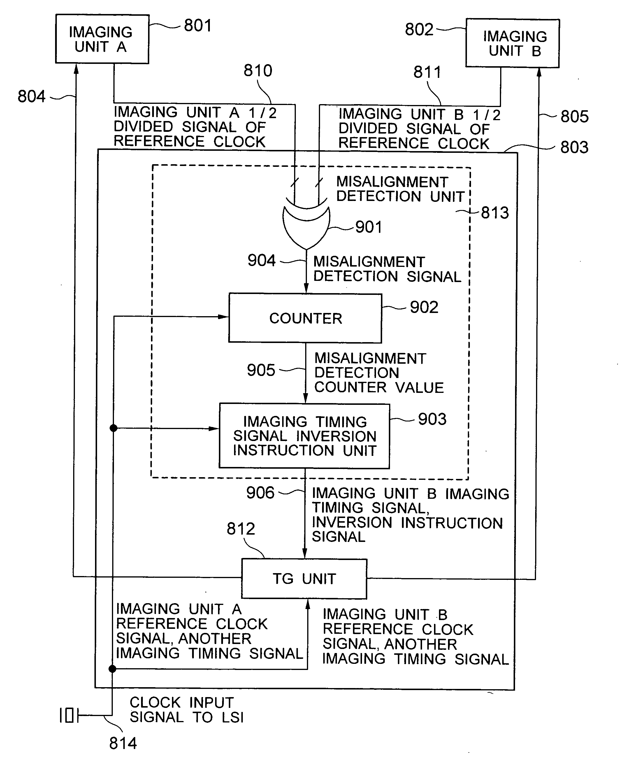
[0076] A vehicle mounted stereo camera apparatus according to a third embodiment of the present invention will be described below with reference to FIGS. 8A-8B and 9. FIGS. 8A-8B are block diagrams showing configurations of vehicle mounted stereo camera apparatus according to the third embodiment of the invention. FIG. 9 is a diagram showing a configuration example using different kinds of imaging units in a vehicle mounted stereo camera apparatus according to the third embodiment.

[0077] In vehicle mounted stereo camera apparatus according to the third embodiment, not CCD (Charge Coupled Device) sensors but CMOS (Complementary Metal-Oxide Semiconductor) sensors 130 are used in imaging units. As shown in the configuration example of FIG. 8A, each CMOS sensor 130 typically includes a timing generator TG 131 interiorly. In this TG built-in configuration, timing is generated by the TG 131 of each sensor 130 individually. It is therefore difficult to synchronize the sensors 130 with eac...


PUM


Abstract

A vehicle mounted stereo camera apparatus including a plurality of imaging units for generating image data sequentially based on optical information from an object, and an image processing unit for importing the image data generated by the plurality of imaging units respectively, processing the imported image data individually, and then performing a stereo image process operation. The image data input into the image processing unit are synchronized with clock signals for importing and processing the image data respectively. Thus, the stereo image process operation is performed without horizontal pixel misalignment between image data A and B from the plurality of imaging units, so as to attain a stereo matching process with a high accuracy.

Description

BACKGROUND OF THE INVENTION [0001] The present invention relates to a stereo camera apparatus and a stereo image process technique, and particularly relates to a stereo camera apparatus in which imaging timing and image input timing are adjusted in a stereo image process. [0002] A stereo camera apparatus in which a distance to an object is calculated using a pair of images taken by two imaging units, and the object is recognized based on the calculated distance has begun to be applied to a supervisory system for detecting entry of a suspicious person or abnormality or a vehicle mounted system for assisting a driver to drive safely. [0003] The stereo image process used in the supervisory system or the vehicle mounted system is to apply a triangular surveying technique to a pair of images taken at a positional interval so as to obtain a distance. The stereo image processing apparatus typically has a pair of imaging units and a stereo image processing LSI for applying a triangular surv...

Claims


Application Information

Patent Timeline
Patent Type & Authority Applications(United States)
IPC IPC(8): G05D1/00G06K9/00H04N7/18H04N13/00
CPCH04N13/0239H04N13/0296H04N13/239H04N13/296
Inventor YOKOTA, SOICHIROMURAMATSU, SHOJIOSAKA, ICHIRO
Owner HITACHI LTD
Why Eureka
Try Eureka