

Method and apparatus for noninvasive targeting
a non-invasive and tissue technology, applied in the field of non-invasive sampling, can solve the problems of primary interference in tissue analysis, achieve the effects of enhancing the signal of a non-invasive signal, and improving the accuracy and precision of non-invasive analyte property estimation
- Summary
- Abstract
- Description
- Claims
- Application Information
AI Technical Summary
Benefits of technology
Problems solved by technology
Method used
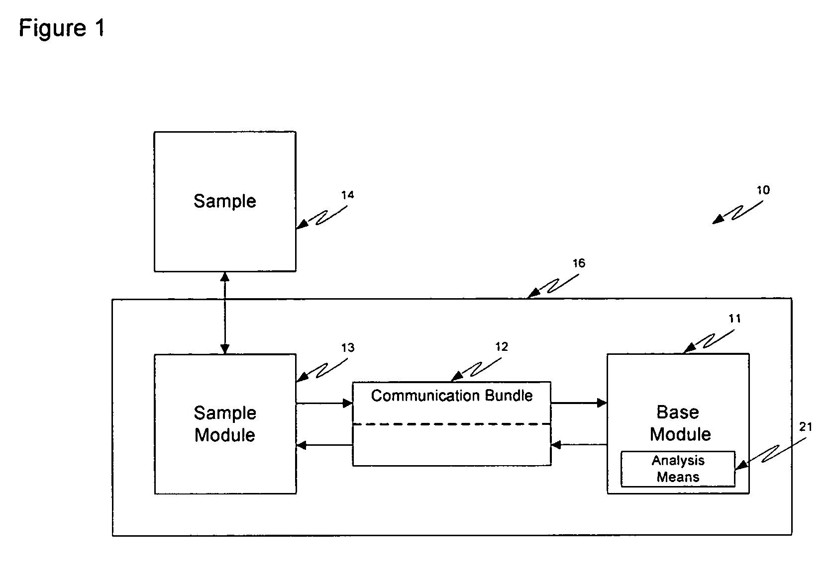
Image

Examples
example i
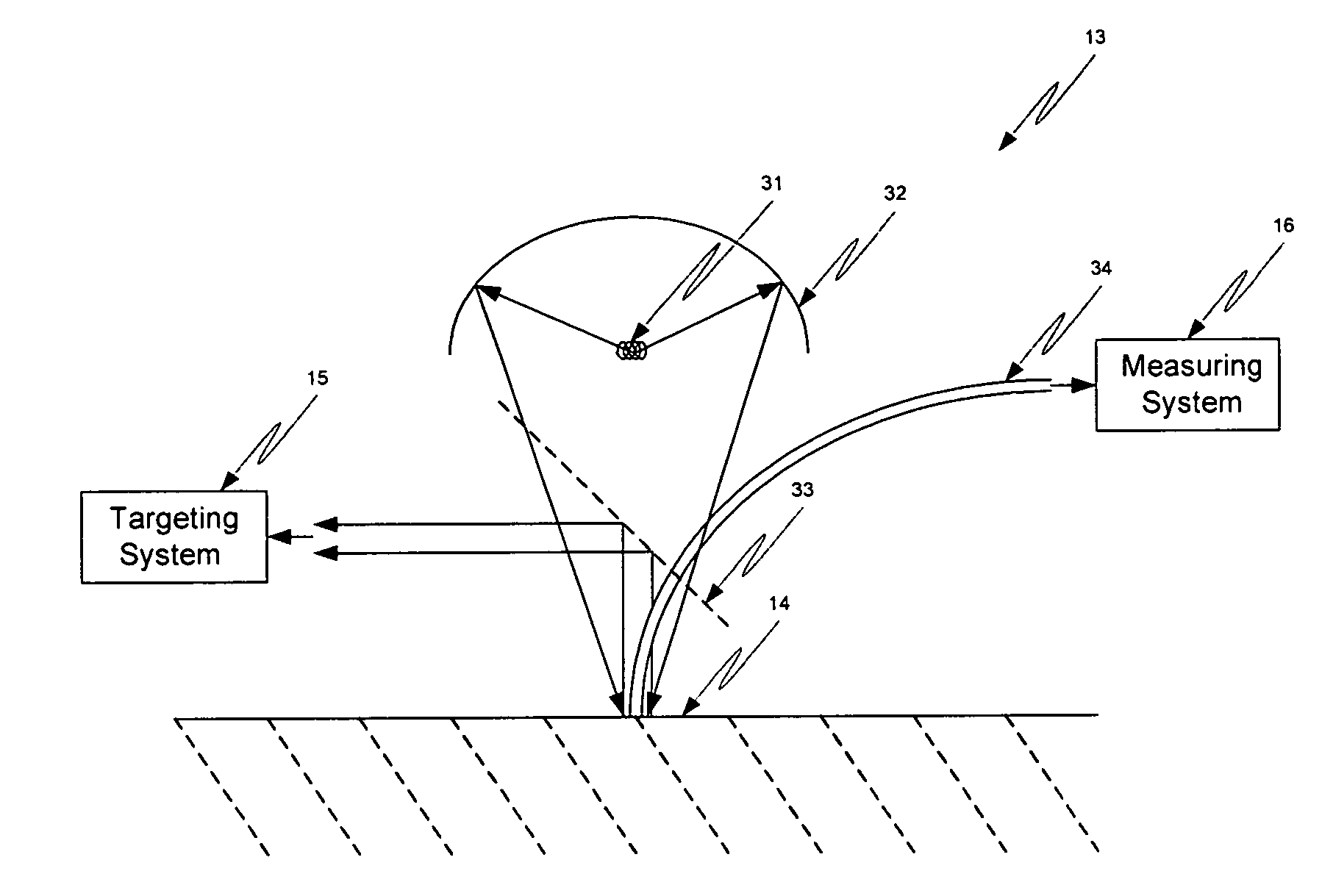
[0063] In a first example, a cutaneous sampling optical probe uses a distance between incident photons directed at the skin and the collected photons coming from the skin to control average depth of penetration and / or average optical pathlength of the probing photons. Optional distances include a minimum distance, a maximum distance, and both a minimum and maximum distance. For example, very short pathlengths are effectively blocked using a distance, such as about 0.1, 0.3, 0.5, 0.7, 1, 2, or 3 mm, between a region of incident photons contacting the skin and a region where photons are collected from the skin. Blocking photons is accomplished by a number of means including use of any of a thin or thick blocker, such as a blade, a gap, a spacer, and an optically opaque sheath, such as a fiber optic coating. This spacer is optionally used to block specular light in embodiments where the optics contact or come into close proximity with the skin. A maximum range is defined by the far rea...
example ii
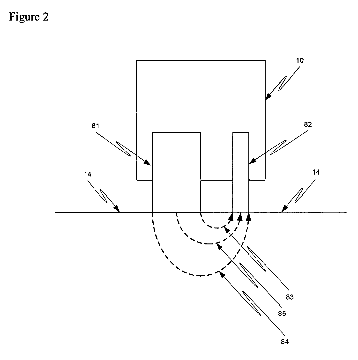
[0064] Referring now to FIG. 2, an example of an analyzer 10 with a given pathlength and / or optical depth is provided. An illumination probe 81 delivers photons to the tissue sample 14. A collection probe 82 collects light emerging from a collection area. On average, short depths and short photonic pathlengths in tissue result from photons with the shortest distance to travel 83. Photons having the longest distance to travel between the illumination area and collection area typically have the largest average depth of penetration and pathlength 84. Intermediate distances typically result in intermediate depths of penetration and pathlength 85. The average pathlength and depth of penetration is increased by moving the illumination area further from the collection area. Similarly, smaller pathlengths and shallower penetration depths are achieved by moving the illumination area closer to the collection area. By controlling the illumination area(s), collection area(s), sizes and location...
example iii
[0065] In a third example of the invention, a fiber bundle or a plurality of bundlets are used to control the analyte signal through controlling variables, such as pathlength and / or depth of penetration. The spacing between the illumination and collection fibers of each bundlet, and the spacing between bundlets is optimized to minimize sampling of the adipose subcutaneous layer and to maximize collection of light that has been backscattered from the cutaneous layer. This example optimizes penetration depth by limiting the range of distances between illumination fibers and detection fibers. By minimizing sampling of the adipose layer, interference contributed by the fat band is greatly reduced in the sample spectrum, thereby increasing the signal-to-noise ratio for the target analyte. In addition, by maximizing photonic sampling of an aqueous rich layer, such as the dermis, analyte signal for hydrophilic analytes, such as glucose, are enhanced. Similarly, maximizing photonic sampling...
PUM
 Abstract
Description
Claims
Application Information