
Oilfield enhanced in situ combustion process

a combustion process and oilfield technology, applied in drinking water installation, wellbore/well accessories, construction, etc., can solve the problems of sand retention screen failure and irreparable damage to the wellbore, and achieve the effect of increasing the mobility of hydrocarbons, increasing the recovery rate, and adequate partial solubility

Inactive Publication Date: 2006-09-21
ARCHON TECH LTD
View PDF14 Cites 35 Cited by
  • Summary
  • Abstract
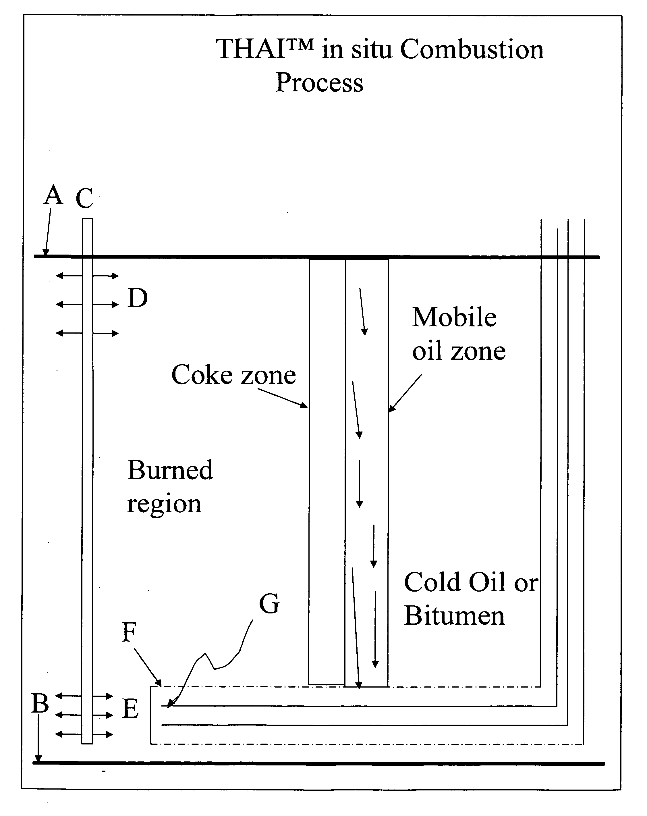
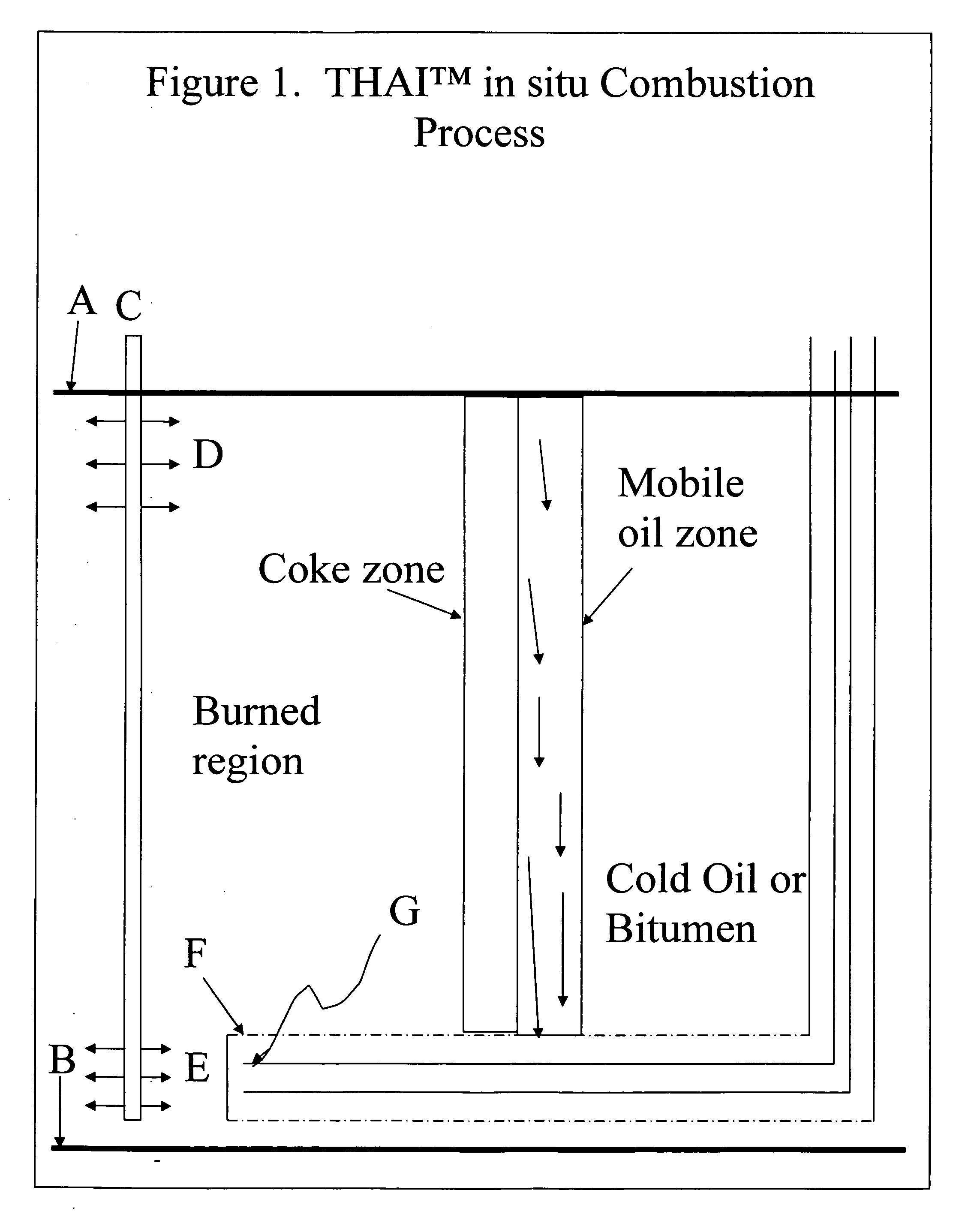
  • Description
  • Claims
  • Application Information

AI Technical Summary

Benefits of technology

[0007] During the reservoir pre-heating phase, or start-up procedure, steam is circulated in the horizontal well through a tube that extends to the toe of the well. The steam flows back to the surface through the annular space of the casing. This procedure is imperative in bitumen reservoirs because cold oil that may enter the well will be very viscous and will flow poorly, possible plugging the wellbore. Steam is also circulated through the injector well and is also injected into the reservoir in the region between the injector wells and the toe of the horizontal wells to warm the oil and increase its mobility prior to initiating injection of oxidizing gas into the reservoir.
[0008] The aforementioned Patents show that with continuous oxidizing gas injection a quasi-vertical combustion front develops and moves laterally from the direction of the toe of the horizontal well towards the heel. Thus two regions of the reservoir are developed relative to the position of the combustion zone. Towards the direction of toe, lies the oil-depleted region that is filled substantially with oxidizing gas, and on the other side lies the region of the reservoir containing cold oil or bitumen. At higher oxidant injection rates, reservoir pressure increases and the fuel deposition rate can be exceeded, so that gas containing residual oxygen can be forced into the horizontal wellbore in the oil-depleted region.
[0012] Specifically, when the injected non-oxidizing gas which is injected with oxygen comprises only carbon dioxide in the absence of nitrogen, the improvement can be dramatic.
[0017] It is not required that the CO2 be miscible (ie. soluble in all proportions) in the oil under reservoir conditions. Partial solubility is adequate.
[0018] While the mechanics of how adding a particular non-oxidizing gas such as CO2, as opposed to other non-oxidizing gases, further increases the mobility of hydrocarbons in a reservoir are not precisely understood, and without being in any way held to an explanation as to why such important increases in recoverability are obtained as a result of CO2 injection, it is suspected that CO2 acts as a solvent and decreases the oil viscosity ahead of the combustion zone, thereby enhancing the combustion process and thus further liquefying oil ahead of the combustion zone. The added dissolution of some CO2 in the combustion front also facilitates the transfer of heat from the combustion gas into the oil, which also reduces the oil viscosity, thus increasing recovery.

Problems solved by technology

This procedure is imperative in bitumen reservoirs because cold oil that may enter the well will be very viscous and will flow poorly, possible plugging the wellbore.
The consequence of having oil and oxygen together in a wellbore is combustion and potentially an explosion with the attainment of high temperatures, perhaps in excess of 1000° C. This can cause irreparable damage to the wellbore, including the failure of the sand retention screens.

Method used


Image

  • Oilfield enhanced in situ combustion process
  • Oilfield enhanced in situ combustion process
  • Oilfield enhanced in situ combustion process

Examples


example 1

[0109] Table 1a shows the simulation results for an air injection rate of 65,000 m3 / day (standard temperature and pressure) into a vertical injector (E in FIG. 1). The case of zero steam injected at the base of the reservoir at point I in well J is not part of the present invention. At 65,000 m3 / day air rate, there is no oxygen entry into the horizontal wellbore even with no steam injection and the maximum wellbore temperature never exceeds the target of 425° C.

[0110] However, as may be seen from the data below, injection of low levels of steam at levels of 5 and 10 m3 / day (water equivalent) at a point low in the reservoir (E in FIG. 1) provides substantial benefits in higher oil recovery factors, contrary to intuitive expectations. Where the injected medium is steam, the data below provides the volume of the water equivalent of such steam, as it is difficult to otherwise determine the volume of steam supplied as such depends on the pressure at the formation to which the steam is s...

example 2

[0111] Table 1b shows the results of injecting steam into the horizontal well via the internal tubing, G, in the vicinity of the toe while simultaneously injecting air at 65,000 m3 / day (standard temperature and pressure) into the upper part of the reservoir. The maximum wellbore temperature is reduced in relative proportion to the amount of steam injected and the oil recovery factor is increased relative to the base case of zero steam. Additionally, the maximum volume percent of coke deposited in the wellbore decreases with increasing amounts of injected steam. This is beneficial since pressure drop in the wellbore will be lower and fluids will flow more easily for the same pressure drop in comparison to wells without steam injection at the toe of the horizontal well.

TABLE 1bAIR RATE 65,000 m3 / day- Steam injected in well tubing.SteamInjectionMaximum wellMaximum cokeMaximum OxygenBitumen recoveryAverage oilRate m3 / dayTemperature,in wellborein wellboreFactorProduction(water equivale...

example 3

[0112] In this example, the air injection rate was increased to 85,000 m3 / day (standard temperature and pressure) and resulted in oxygen breakthrough as shown in Table 2a. An 8.8% oxygen concentration was indicated in the wellbore for the base case of zero steam injection. Maximum wellbore temperature reached 1074° C. and coke was deposited decreasing wellbore permeability by 97%. Operating with the simultaneous injection of 12 m3 / day (water equivalent) of steam at the base of the reservoir via vertical injection well C (see FIG. 1)provided an excellent result of zero oxygen breakthrough, acceptable coke and good oil recovery.

TABLE 2aAIR RATE 85,000 m3 / day- Steam injected at reservoir base.SteamInjectionMaximum wellMaximum cokeMaximum OxygenBitumen recoveryAverage oilRate m3 / dTemperature,in wellborein wellboreFactorProduction(water equivalent)° C.%%% OOIPRate m3 / day*01074978.8 55188001241443036.133.4

*Not part of the present invention.


PUM


Abstract

A process for improved safety and productivity when undertaking oil recovery from an underground reservoir by the toe-to-heel in situ combustion process employing a horizontal production well. Water, steam, and / or a non-oxidizing gas, which in the preferred embodiment substantially comprises carbon dioxide which acts as a gaseous solvent, is injected into the reservoir for improving recovery in an in situ combustion recovery process, via either an injection well, a horizontal well, or both.

Description

RELATED APPLICATIONS [0001] This application is a continuation-in-part of PCT application PCT / CA2005 / 000883 filed on Jun. 6, 2005 in which the United States was designated, claiming priority from U.S. Provisional Application 60 / 577,779 filed Jun. 7, 2004, each of which are incorporated herein by reference in their entirety and for all their teachings, disclosures and purposes.FIELD OF THE INVENTION [0002] This invention relates to a process for improved safety and productivity when undertaking oil recovery from an underground reservoir by the toe-to-heel in situ combustion process employing horizontal production wells, such as disclosed in U.S. Pat. Nos. 5,626,191 and 6,412,557. More particularly, it relates to an in situ combustion process in which a water, steam, and / or a non-oxidizing gas which in a preferred embodiment is carbon dioxide which acts as a gaseous solvent, is injected into the reservoir for improving recovery in an in situ combustion recovery process. BACKGROUND OF ...

Claims


Application Information

Patent Timeline
Patent Type & Authority Applications(United States)
IPC IPC(8): E21B43/24E21B43/243
CPCE21B43/243E21B43/305
Inventor AYASSE, CONRAD
Owner ARCHON TECH LTD
Learn More