Mist spraying apparatus and method, and image forming apparatus

a spraying apparatus and spraying technology, applied in printing and other directions, can solve the problems of essentially impossible to avoid the enlargement of the dot diameter when the ink lands on the medium, the deposition performance actually becoming worse, and the subject of high variations, so as to improve the deposition performance, reduce the amount of charge, and increase the acceleration energy

Inactive Publication Date: 2006-09-21
FUJIFILM CORP
View PDF2 Cites 25 Cited by
  • Summary
  • Abstract
  • Description
  • Claims
  • Application Information

AI Technical Summary

Benefits of technology

[0029] According to the present invention, the functions of charging and acceleration are separated either spatially or temporally, and the acceleration energy is ra...

Problems solved by technology

Since the mist is a collection (cluster) of fine liquid droplets, it is highly subject to variations caused by prolongation in the flight time of the liquid droplets due to the effects of air resistance, and disturbance by external air flows.
Therefore, a device is used to accelerate the movement of the fine liquid droplets forming the mist cluster by charging the droplets and applying an electric fiel...

Method used


Image

  • Mist spraying apparatus and method, and image forming apparatus
  • Mist spraying apparatus and method, and image forming apparatus
  • Mist spraying apparatus and method, and image forming apparatus

Examples


first embodiment

Method

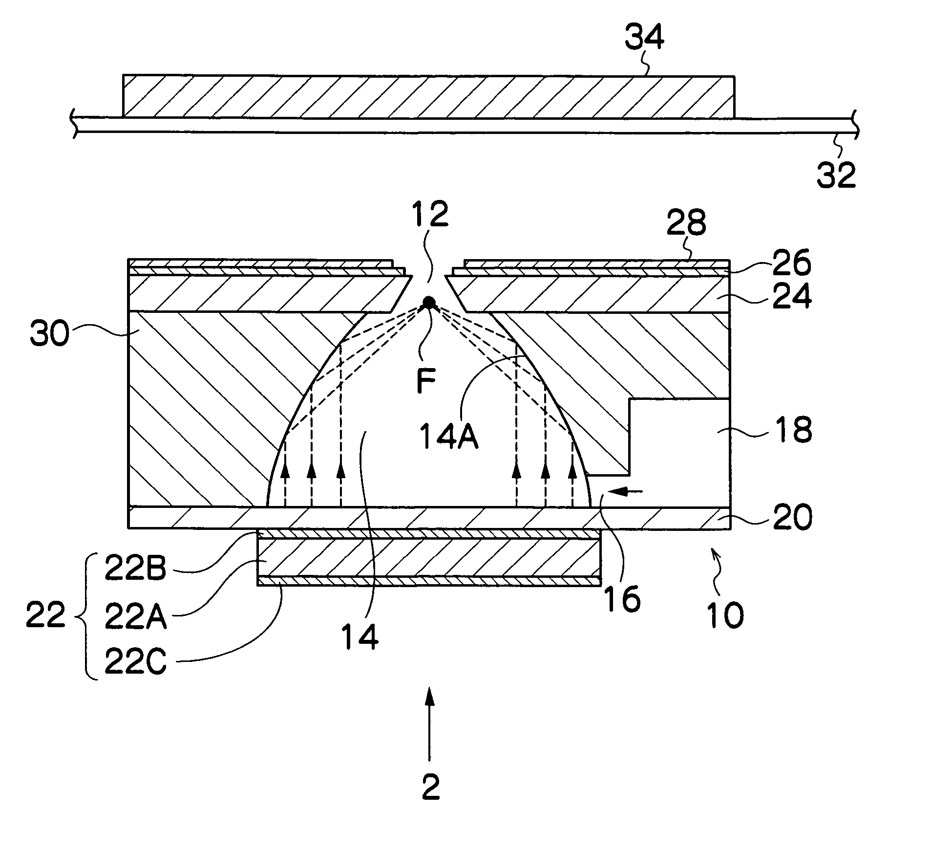
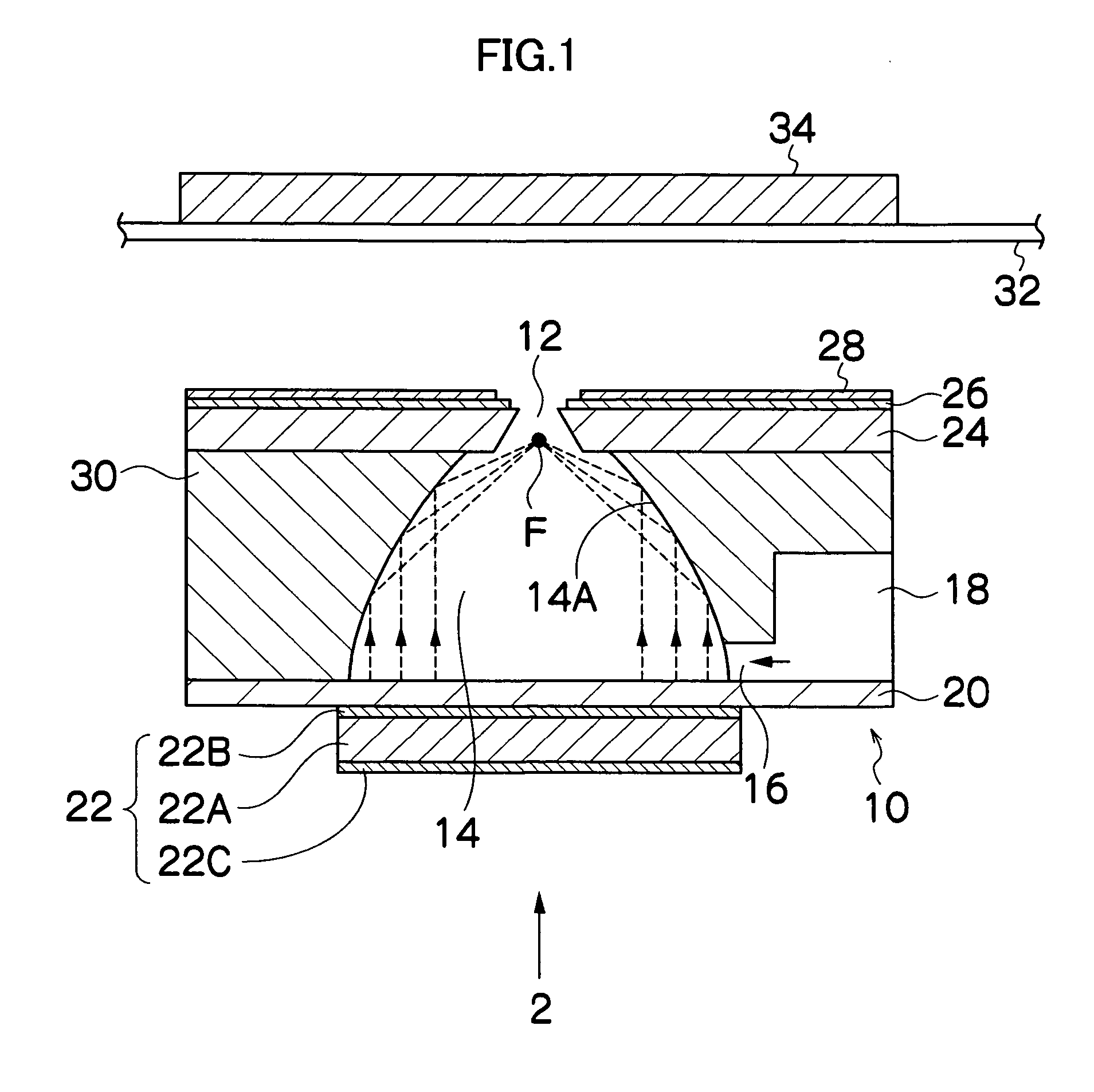
[0045]FIG. 1 is a cross-sectional diagram showing the basic composition of a mist spraying apparatus according to a first embodiment of the present invention. The mist spraying apparatus 10 shown in FIG. 1 includes a nozzle 12, an ink chamber 14, an ink supply port 16, a common flow channel 18 which accommodates ink to be supplied to the ink chamber 14, an insulating resin film 20, and a piezoelectric element 22. FIG. 1 shows a cross-sectional view of an ink chamber unit corresponding to one nozzle 12 (the liquid droplet ejection element for one channel). When applied to a mist ejection head, such as a print head (also called a “recording head”), or the like, a structure comprising a plurality of channels arranged one-dimensionally (in a column shape) or two-dimensionally (in a plane shape) is adopted.

[0046] The nozzle plate 24 in which the nozzles (ejection ports) 12 are formed is constituted by a conducting material, such as metal, and also serves as an electrode for chargi...

second embodiment

Method

[0063]FIGS. 5A and 5B are enlarged schematic drawings showing the principal composition of a mist spraying apparatus according to a second embodiment of the present invention. In FIGS. 5A and 5B, members which are the same as or similar to the composition in FIG. 3 are denoted with the same reference numerals and description thereof is omitted here. The embodiments shown in FIGS. 1 to 4 have the composition in which the electrode performing the charging function (nozzle plate 24), and the electrode performing the acceleration function (acceleration electrode 28) are separated spatially. On the other hand, the embodiment shown in FIGS. 5A and 5B is a mode which uses the nozzle plate 24 that serves as an electrode for both charging and acceleration (in this case, the nozzle plate corresponds to a charging and acceleration electrode), and a power source having a controllable voltage output (for example, a multi-output power source) 37, the functions of the electrode being separat...


PUM


Abstract

The mist spraying apparatus comprises: a pressure chamber into which liquid is filled; a charging electrode which is in contact with the liquid and charges the liquid; a vibration generating device which converts the liquid into droplets by applying vibrational energy to the liquid inside the liquid chamber, thereby generating a charged mist; a rear surface electrode which is disposed so as to oppose an ejection surface including an ejection port ejecting the charged mist, and holds an liquid receiving medium onto which the charged mist is deposited from the ejection port; an acceleration electrode which is disposed at a position separated by a prescribed distance in an outward radial direction from an edge of the ejection port, and generates an electric field for acceleration between the acceleration electrode and the opposing rear surface electrode; a charging voltage application device which applies a charging voltage to the charging electrode; and an acceleration voltage application device which applies an acceleration voltage that is higher than the charging voltage to the acceleration electrode, thereby generating, between the acceleration electrode and the rear surface electrode, the electric field for acceleration having an electric field intensity which is greater than an electric field intensity generated between the charging electrode and the rear surface electrode by the voltage applied from the charging voltage application device.

Description

BACKGROUND OF THE INVENTION [0001] 1. Field of the Invention [0002] The present invention relates to a mist spraying apparatus and method, and an image forming apparatus, and more particularly to an apparatus and method for spraying a liquid in the form of a mist, by using ultrasonic waves, and to an image forming apparatus which records images by means of a group of ink micro-particles (ink mist) sprayed as a mist. [0003] 2. Description of the Related Art [0004] There is an ink mist type of image recording apparatus (ink mist printer) which records images by generating a flow of ink mist (very fine ink particles) by means of ultrasonic vibration, and depositing this ink mist onto a recording medium as a group (cluster), (see, for example, Japanese Patent Application Publication Nos. 62-85948, 62-111757, 2-134250 and 5-57891). Furthermore, a composition of a print head using concentrated ultrasonic waves and nozzles has also been proposed (“Study on Ink Ejection of Print Head Using ...

Claims


Application Information

Patent Timeline
IPC IPC(8): B41J2/06
CPCB41J2/14008
Inventor ONOZAWA, SHO
Owner FUJIFILM CORP
Why Eureka
Try Eureka