Coordinated directional medium access control in a wireless network

a wireless network and access control technology, applied in the field of electronic communications, can solve the problems of high problem of directional signal and directional antenna use in ad hoc wireless networks, unsolved problems, and deafness, and achieve the effects of increasing energy efficiency, reducing and increasing the number of wireless networks

Inactive Publication Date: 2006-09-21
UNIV OF FLORIDA RES FOUNDATION INC
View PDF15 Cites 83 Cited by
  • Summary
  • Abstract
  • Description
  • Claims
  • Application Information

AI Technical Summary

Benefits of technology

[0015] The present invention provides a method, system, and article of manufacture that achieve within a wireless ad hoc network the advantages of directional transmission and reception—higher throughput, increased energy efficiency, and greater spatial reuse—while maintaining low signaling overhead. The method, system, and article of manufacture are based on a coordinated directional medium access control (CDMAC) protocol, a key feature of which is the introduction of a time-frame structure that facilitates the simultaneous transmission and simultaneous reception of multiple data packets in a wireless ad hoc network.

Problems solved by technology

Despite these definite advantages, the use of directional signals and directional-capable antennas in ad hoc wireless networks remains highly problematic.
The transmission and reception of directional signals via directional-capable antennas in such a network poses several as-yet-unsolved problems.
One problem is the so-called deafness problem, which can be defined in various ways but generally arises when a transmitting node fails to communicate with an intended receiving node because the receiving node is beamformed in a direction away from the transmitting node.
The deafness problem can cause energy to be wasted and network capacity to be squandered in a wireless ad hoc network as a result of network nodes engaging in repeated, unproductive transmissions.
The deafness problem also can degrade the performance of communication systems operating in accordance with conventional routing protocols and transport protocols such as the TCP.
For example, the deafness problem can cause false link-breakage indications in the routing layer and lessen the stability of end-to-end congestion control.
Yet another obstacle to utilizing directional transmissions and receptions in a wireless ad hoc network is the hidden-terminal problem whereby a deaf node transmits an RTS signal in the same beam direction as is being used for an on-going communication between another pair of nodes.
The hidden-terminal condition is a long-recognized problem that arises even in ad hoc wireless networks whereby nodes communicate with one another using only omni-directional antennas.
The problem can be even more severe if directional antennas are employed in such networks, with the result that an ad hoc wireless network using directional antennas may perform less effectively and less efficiently than one using only omni-directional antennas.
Another obstacle to using directional antennas in wireless ad hoc networks is the exposed-terminal problem.
Still another obstacle is the side lobe problem.
The problem can arise if one node senses the RTS / CTS exchange of a pair of other nodes and decides that, since its own anticipated transmission to yet another node will not collide with the beam of the communicating pair of nodes, it can transmit a collision-free signal to the other node.
The problem occurs if the deciding node is in such close proximity to one of the two communicating nodes that a side lobe of the signal from the deciding node interferes with the signal between the communicating nodes.
Yet another obstacle to using directional antennas in wireless ad hoc networks concerns the inefficient use of the directional antenna gain and channel gain realized from such use.
These advantages can be lost or wasted, however, if the network is not capable of responding to such conditions by increasing transmission data rates or reducing transmission power.
Although this proposed solution potentially alleviates the deafness and hidden-terminal problems, it nonetheless can result in a concommitant increase in signaling overhead.

Method used


Image

  • Coordinated directional medium access control in a wireless network
  • Coordinated directional medium access control in a wireless network
  • Coordinated directional medium access control in a wireless network

Examples


Embodiment Construction

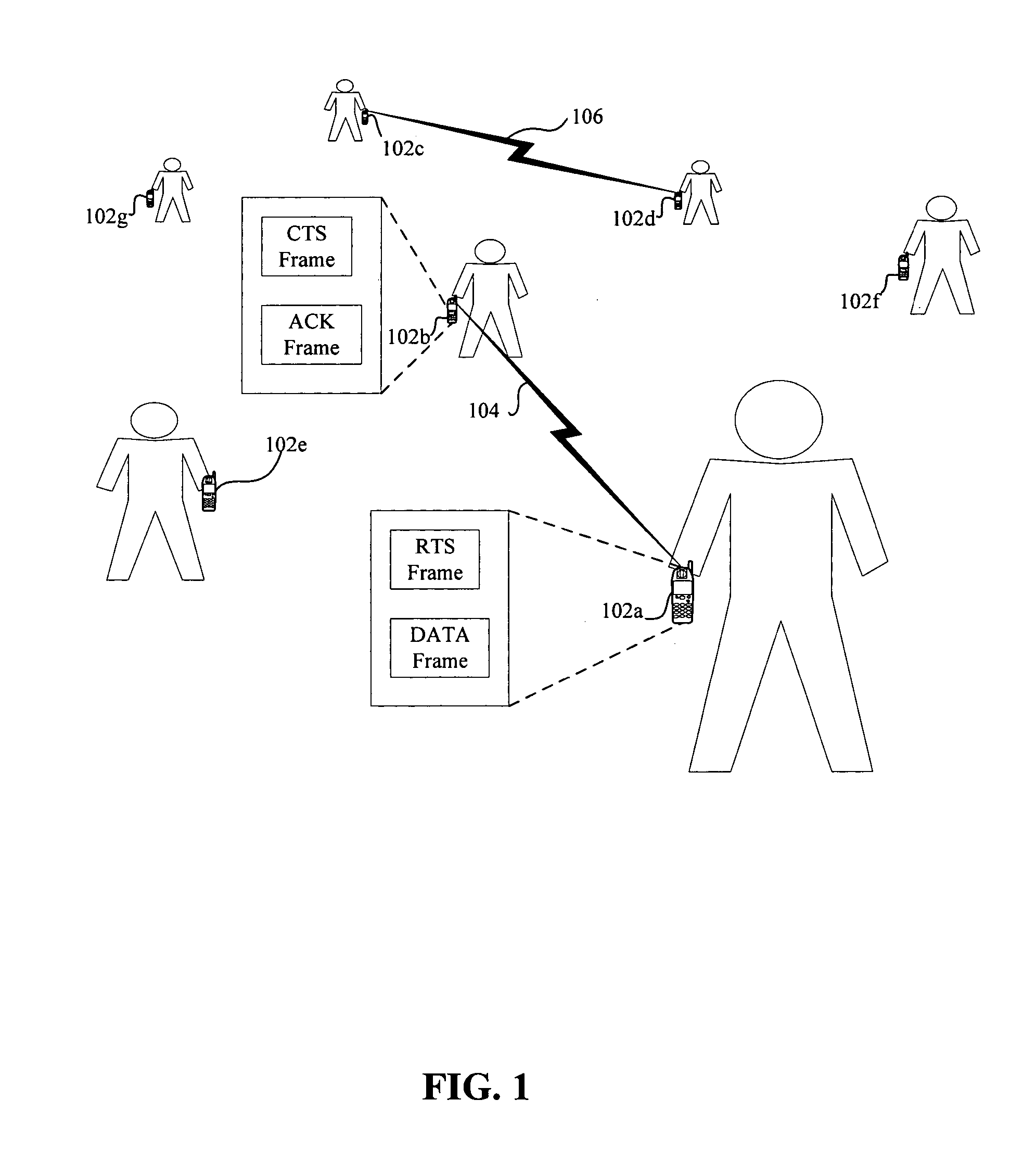
[0030]FIG. 1 provides a schematic diagram of a system 100 for wirelessly transmitting and receiving data packets, according to one embodiment of the present invention. The system 100 illustratively comprises a plurality of nodes, including a master sending node 102a and corresponding master receiving node 102b. The system 100 also illustratively includes another pair of nodes defining a slave sending node 102c and corresponding slave receiving node 102d. Illustratively, the system includes yet additional nodes 102e, 102f, 102g, any pair of which can define an additional slave sending node and corresponding additional slave receiving node selected as described more particularly below. As will be apparent from the ensuing discussion the system 100 can include still other nodes in addition to those shown. In the aggregate the nodes 102a-g define an ad hoc communication network.

[0031] Each of the exemplary nodes 102a-g of the system 100 is a communications node having the capabilities ...


PUM


Abstract

A method of simultaneously transmitting and receiving multiple data packets over wireless channels among the nodes of a wireless network is provided. The method includes automatically selecting a master sending node and corresponding master receiving node in response to an omni-directionally transmitted request to send during a contention period. The method also includes selecting a slave sending node and corresponding slave receiving node if a spatial reuse ratio correspond to the master-node pair is less than a predetermined threshold and if directional data transmissions between the slave sending node and corresponding slave receiving node avoid interfering with directional data transmissions between the master nodes and other pairs of slave nodes. The method further includes causing the master sending node and slave sending node to directionally transmit data packets during a coordination period.

Description

STATEMENT REGARDING FEDERALLY SPONSORED RESEARCH OR DEVELOPMENT [0001] Research related to this invention was funded at least in part by the U.S. Office of Naval Research under Young Investigator Award N000140210464. The U.S. Government may have certain rights in the invention.CROSS-REFERENCE TO RELATED APPLICATIONS [0002] Not applicable. BACKGROUND [0003] 1. Field of the Invention [0004] The present invention is related to the field of electronic communications, and, more particularly, to wireless electronic communications [0005] 2. Description of the Related Art [0006] The transmission and reception of a wireless signal is generally characterized as being either omni-directional or directional. An omni-directional signal radiates outwardly in a 360-degree range, the signal being emitted by an omni-directional antenna. By contrast, a directional signal emitted by a directional antenna travels in a specific beam direction with a particular beamwidth. [0007] The transmission and rece...

Claims


Application Information

Patent Timeline
Patent Type & Authority Applications(United States)
IPC IPC(8): H04Q7/24H04W16/30H04W74/02H04W84/20
CPCH04W16/30H04W74/02H04W84/20
Inventor FANG, YUGUANG MICHAELWANG, JIANFENGWU, DAPENG OLIVER
Owner UNIV OF FLORIDA RES FOUNDATION INC
Why Eureka
Try Eureka