Delivery of therapeutic capable agents

a capable agent and therapeutic technology, applied in the field of medical devices and methods, can solve the problems unable to completely avoid the occurrence of restenosis, and unable to achieve the effect of reducing the occurrence of thrombosis and delay of release of therapeutic capable agents to the susceptible tissue si

Inactive Publication Date: 2006-09-21
ALTAI MEDICAL TECH
View PDF99 Cites 58 Cited by
  • Summary
  • Abstract
  • Description
  • Claims
  • Application Information

AI Technical Summary

Benefits of technology

[0040] In an embodiment, the release of the therapeutic capable agent to the susceptible tissue site may be delayed. During the delay period none to small amounts of therapeutic capable agent may be released before the release of a substantial amount of therapeutic capable agent. Typically, the delay is sufficiently long to allow for sufficient generation of intimal tissue or cellularization at the tre...

Problems solved by technology

While these procedures have gained wide acceptance (either alone or in combination, particularly PTA in combination with stenting), they continue to suffer from significant disadvantages.
A particularly common disadvantage with PTA and other known procedures for opening stenotic regions is the frequent occurrence of restenosis.
Whi...

Method used


Image

  • Delivery of therapeutic capable agents
  • Delivery of therapeutic capable agents
  • Delivery of therapeutic capable agents

Examples


example 1

Preparation of a Drug Eluting Stent According to the Present Invention

[0086] A drug solution at a concentration of 0.030 gram benidipine per ml of Ethanol was prepared. A spray valve reservoir was filled with the drug solution using an EFD 780S Series spray valve with a 0.028″ diameter spray nozzle head (part number 7857-28SS). An 18 mm Duraflex™ stent was provided and weighed (initial weight). A 0.014″ U-shaped wire mandrel was inserted inside the stent. The stent was fixed to a rotating fixture located at about 0.5 inches under the nozzle head. The stent was sprayed with the drug solution with a stroke control knob of the spray valve set at 0.75, reservoir pressure of 12 psi, and nozzle air pressure of 25 psi. While the spray valve was moved horizontally across the length of the stent, the drug solution was sprayed on the surface of the stent. The stent was coated until the desired amount of drug (e.g., 300 μg) was deposited on the stent. The mandrel was removed from the stent an...

example 2

Preparation of a Drug Eluting Stent Having Smooth Drug Coating Layer

[0088] A drug solution at a concentration of 0.030 g of benidipine per ml of Ethanol was prepared. A spray valve reservoir was filled with the drug solution using an EFD 780S Series spray valve with a 0.028″ diameter spray nozzle head (part number 7857-28SS). An 18 mm Duraflex™ stent was provided and weighed (initial weight). A 0.014″ U-shaped wire mandrel was inserted inside the stent. The stent was fixed to a rotating fixture located at about 0.5 inches under the nozzle head. The stent was sprayed with the drug solution with a stroke control knob of the spray valve set at 1, reservoir pressure of 12 psi, and nozzle air pressure of 25 psi. While the spray valve was moved horizontally across the length of the stent, the drug solution was sprayed on the surface of the stent until the desirable amount of drug (e.g., 300 μg) was deposited on the stent. The mandrel was removed from the stent and the stent was let dry i...

example 3

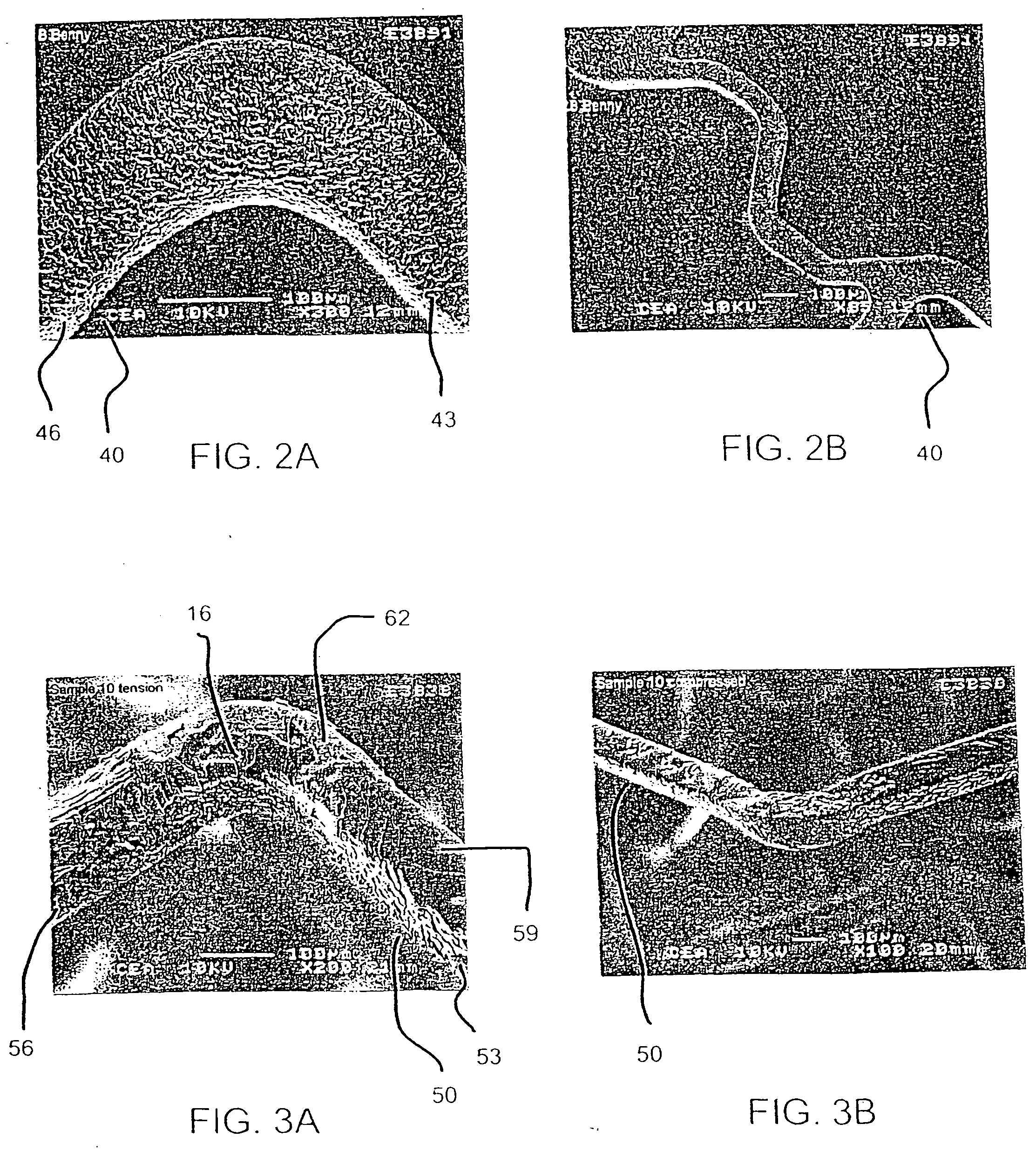
[0090] In an effort to evaluate the effect of drug layer surface characteristics on drug loss from a drug eluting stent upon expansion, two groups of stents with two stents in each group, were prepared to include a different drug layer, mycophenolic acid and benidipine, respectively. Within each group, a drug solution was applied to 18 mm length stents according to the procedures described above in reference to Examples 1 and 2. In the case of the mycophenolic acid stents, about 300 μg of the drug solutions was applied in the form of a solution at a concentration of 0.010 mg / ml with a stroke control knob setting being set at 1.0 and 1.5, respectively, to obtain textured and smooth drug coating layers.

[0091] Each of the drug eluting stents was then expanded with a 3.0 mm×18 mm balloon. The balloon was then removed from the stent, the stent was weighed (expanded weight), and the weight of drug loss due to expansion (weight before expansion (e.g., final weight) minus the weight after ...


PUM

PropertyMeasurementUnit
Fractionaaaaaaaaaa
Thicknessaaaaaaaaaa
Thicknessaaaaaaaaaa

Abstract

The present invention provides improved stents and other prostheses for delivering substances to vascular and other luminal and intracorporeal environments. In particular, the present invention provides for therapeutic capable agent eluting stents with minimized undesirable loss of the therapeutic capable agent during expansion of the stent.

Description

CROSS-REFERENCES TO RELATED APPLICATIONS [0001] This application claims the benefit of priority from U.S. Provisional Patent Application Nos. 60 / 370,703, filed on Apr. 6, 2002, 60 / 355,317, filed Feb. 7, 2002, and 60 / 347,473, filed on Jan. 10, 2002; and is a continuation-in-part of U.S. patent application Ser. No. 10 / 002,595, filed on Nov. 01, 2001, which claims the benefit of priority from U.S. Provisional Patent Application No. 60 / 308,381, filed on Jul. 26, 2001, and is a continuation-in-part of U.S. patent application Ser. Nos. 09 / 783,253, 09 / 782,927, 09 / 783,254, 09 / 782,804 all of which were filed on Feb. 13, 2001 and claim the benefit of priority from U.S. Provisional Patent Application No. 60 / 258,024, filed on Dec. 22, 2000; and is a continuation-in-part of U.S. patent application Ser. No. 10 / 017,500, filed on Dec. 14, 2001. Each of the above applications is assigned to the assignee of the present application, the full disclosure of each which is incorporated herein by reference...

Claims


Application Information

Patent Timeline
IPC IPC(8): A61F2/90A61F2/00A61F2/06A61L27/00A61F2/84A61K31/17A61K31/185A61K31/192A61K31/277A61K31/352A61K31/365A61K31/366A61K31/401A61K31/404A61K31/4353A61K31/436A61K31/4375A61K31/4422A61K31/45A61K31/453A61K31/4545A61K31/4709A61K31/472A61K31/519A61K31/52A61K31/551A61K31/554A61K31/565A61K31/573A61K31/675A61K31/7056A61K31/7068A61K38/00A61K39/395A61K45/00A61L31/00A61L31/16A61P3/14A61P7/02A61P7/04A61P9/08A61P9/10A61P29/00A61P31/12A61P35/00A61P37/04A61P37/06A61P43/00
CPCA61F2/91A61F2/915A61F2002/91533A61F2002/91558A61F2230/0054A61F2250/0067A61F2250/0068A61L31/16A61L2300/416A61F2002/91583A61P29/00A61P3/14A61P31/12A61P35/00A61P37/04A61P37/06A61P43/00A61P7/02A61P7/04A61P9/08A61P9/10
Inventor SIRHAN, MOTASIMYAN, JOHN
Owner ALTAI MEDICAL TECH
Why Eureka
Try Eureka