
Mass spectrometric system and mass spectrometry

a mass spectrometry and mass spectrometry technology, applied in the field of mass spectrometry system and analysis method, can solve the problems of complicated operation and complicated operation, and achieve the effect of high accuracy

Inactive Publication Date: 2006-09-28
NEC CORP
View PDF6 Cites 34 Cited by
  • Summary
  • Abstract
  • Description
  • Claims
  • Application Information

AI Technical Summary

Benefits of technology

The present invention provides a technology for efficiently performing sample separation and mass spectrometric analysis with high accuracy. The invention includes a mass spectrometry system comprising a microchip with a channel through which a sample passes, a light irradiation unit that irradiates the sample while moving the laser beam along the sample separation area, and an analytical unit that analyzes the fragment of the sample generated by the laser beam. The system is designed to directly ionize the sample, resulting in a two-dimensional profile that can be obtained without the need for identifying the component of the sample. The system can also separate the sample based on its molecular weight, surface hydrophobic property, or isopotential point. The separated sample is efficiently ionized and moved into the mass spectrometer, allowing for high accuracy in the analysis. The invention also provides a sample separation area that can efficiently separate various components of the sample and perform mass spectrometric analysis based on their properties. The system can also use a plural columnar body design to separate and fractionate various minute size substances. Overall, the invention provides a technology for accurate and efficient mass spectrometric analysis.

Problems solved by technology

Therefore, it is necessary that the separation process and the sample preparation process are separately performed, which complicates the operation.
Therefore, the separation and the analysis of the sample are not continuous, and the operation is relatively complicated.

Method used


Image

  • Mass spectrometric system and mass spectrometry
  • Mass spectrometric system and mass spectrometry
  • Mass spectrometric system and mass spectrometry

Examples


first embodiment

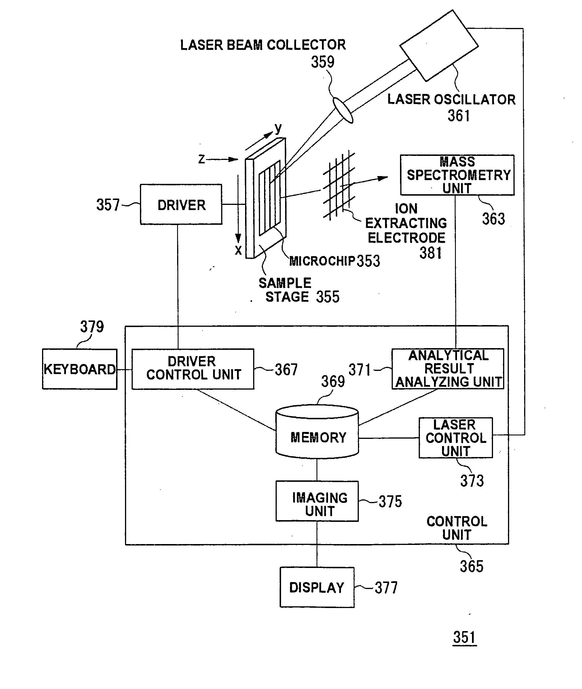
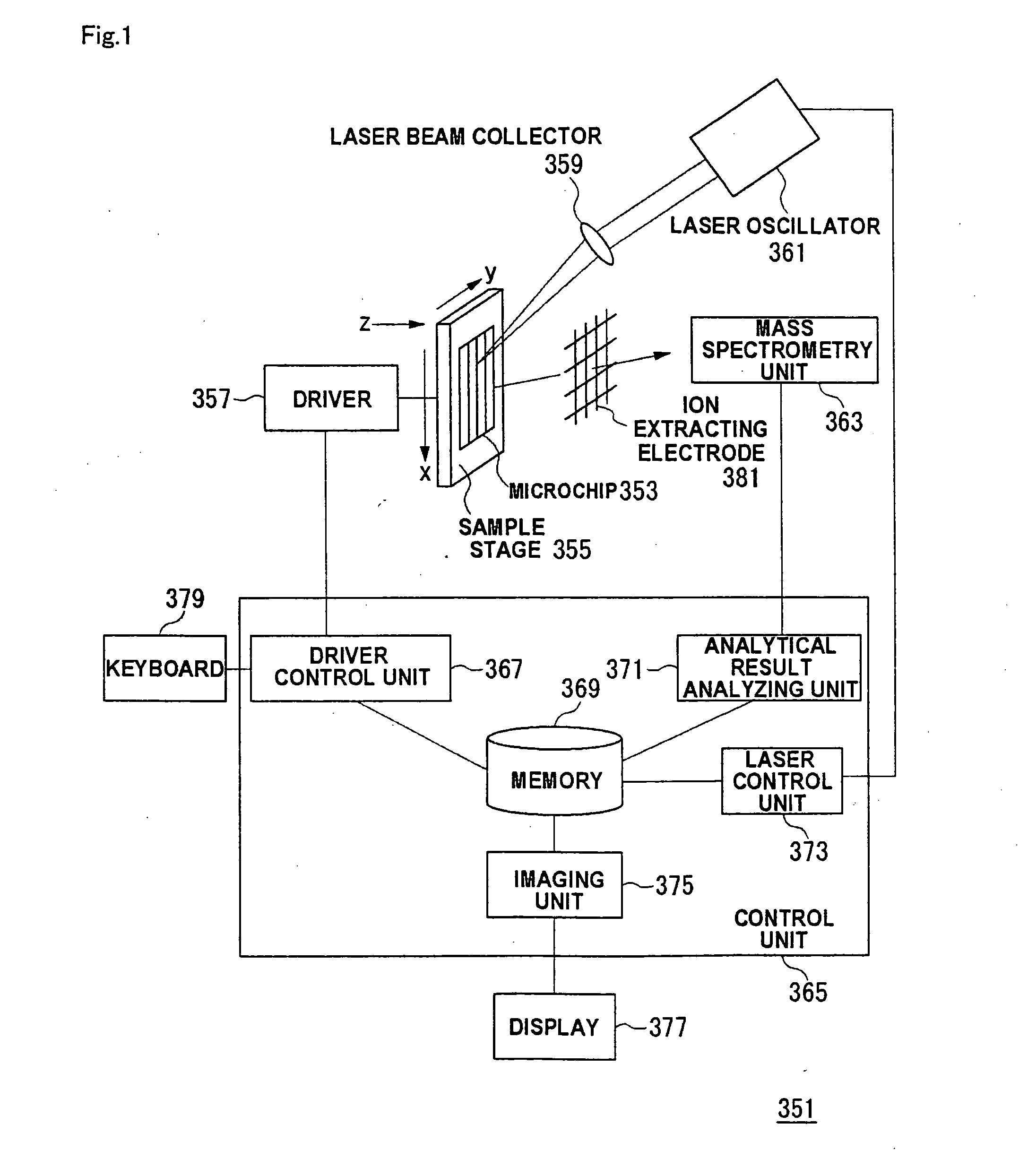
[0160]FIG. 1 is a view showing a configuration of a mass spectrometry system according to the embodiment. In a mass spectrometry system 351 of FIG. 1, a channel (not shown) formed in a microchip 353 on a sample stage 355 is irradiated with a laser beam emitted from a laser oscillator 361, and a sample separated in the channel is ionized. At this point, the laser beam emitted from the laser oscillator 361 is condensed by a laser beam collector 359 and irradiated along the channel on the microchip 353. Therefore, after the sample is previously separated into plural components in the channel on the microchip 353, the channel is irradiated with the laser beam along a separation direction, which allows each separated fraction to be sequentially ionized. A mass spectrometry unit 363 detects the ionized fragment through an ion extracting electrode 381.

[0161] During the laser irradiation along the channel, the position of the channel on the microchip 353 is moved by a driver 357 which adju...

second embodiment

[0223] In the mass spectrometry system of FIG. 1, the microchip 353 may be configured to have the plural channels intersecting one another. FIG. 21 is a view showing the configuration of the microchip 307 which can be applied to the mass spectrometry system 351.

[0224] Similarly to the microchip 307 of FIG. 3, in FIG. 21, the separation channel 112 is also formed in the substrate 110. An charging channel 111 is formed so as to intersect the separation channel 112. Liquid reservoirs 101a and 101b and liquid reservoirs 102a and 102b are formed at the both ends of the separation channel 111 and the charging channel 112. The electrode (not shown) is provided in each liquid reservoir, and the voltage can be applied to the both ends of the separation channel 112 in the same way as the first embodiment. Appropriate values are selected as the outside dimensions of the microchip 307 according to the application. Usually, as shown in FIG. 21, the longitudinal value ranges 5 mm to 5 cm and the...

third embodiment

[0230] The method of moving the sample by applying the voltage is adopted in the microchip 307 described in the first embodiment and the second embodiment. The method of applying the pressure can also be adopted instead of the voltage. FIG. 23 shows an example of the microchip adopting the pressure applying method. Referring to FIG. 23, in the separation chip, female joints are fixed to liquid reservoir portions are located on the ends of a charging channel 19 and a separation channel 20. Male joints, which are coupled to a hollow tube 13, tubes 14 to 16, are connected to the female joints respectively. The reason why the joints 17 are used is to prevent liquid leakage is prevented. For example, FIG. 24 shows the specific configuration of the joint 17.

[0231] The tubes connected to the male joints are coupled to solenoid valves 10, 4, 5, 11 respectively. The buffer solution is supplied from a liquid reservoir 7 to the solenoid valve 10 through a separation pump 8 and a constant-rate...


PUM

PropertyMeasurementUnit
voltageaaaaaaaaaa
heightaaaaaaaaaa
wavelengthsaaaaaaaaaa

Abstract

After a sample is previously separated into plural components in a channel formed in a microchip (353), the channel is irradiated along a separation direction with a laser beam from a laser oscillator (361) to sequentially ionize each fraction separated in the channel. The ionized fraction is detected by a mass spectrometry unit (363) and analyzed by an analytical result analyzing unit (371). The analytical result is stored in a memory (369) while associated with position information in a driver control unit (367) and information on laser beam irradiation condition in a laser control unit (373), and the analytical result is imaged by an imaging unit (375). The imaged analytical result is displayed on a display (377).

Description

TECHNICAL FIELD [0001] The present invention relates to a mass spectrometry system and a method for analysis. BACKGROUND ART [0002] In the analysis of biological samples such as cells and biological materials such as proteins and nucleic acids, an operation for previously separating and purifying the sample and an operation for separating the sample according to sizes or electric charge are performed prior to the analysis. For example, in proteomics analysis, usually mass spectrometric analysis is used for the analysis of a separated component. When the component contained in the sample provided for the mass spectrometric analysis is a bilogical component such as a protein, a nucleic acid, and a polysaccharide, conventionally it is necessary that the target component is previously isolated from the biological sample. For example, when the analysis of the sample containing the plural components is performed, the sample has been purified, the separation has been performed in each comp...

Claims


Application Information

Patent Timeline
Patent Type & Authority Applications(United States)
IPC IPC(8): H01J49/00B01D59/44G01N1/00G01N30/84H01J49/04
CPCB01L3/502746B01L3/502753B01L2200/0663B01L2200/10B01L2300/0681B01L2300/0816B01L2300/16B01L2400/086G01N1/22G01N30/84G01N2030/8452H01J49/0418
Inventor TAKAHASHI, KATSUTOSHIIIDA, KAZUHIROBABA, MASAKAZUIGUCHI, NORIYUKISANO, TORUKAWAURA, HISAOSAKAMOTO, TOSHITSUGUHATTORI, WATARUSOMEYA, HIROKO
Owner NEC CORP
Learn More